Separator for fuel cells and method for producing same

Active Publication Date: 2018-03-22
HONDA MOTOR CO LTD +1
View PDF6 Cites 1 Cited by
  • Summary
  • Abstract
  • Description
  • Claims
  • Application Information

AI Technical Summary

Benefits of technology

The present invention provides a fuel cell separator and a method of producing it that can prevent burrs from being produced at the outer end of the seal member. The structure is simple and easy to produce. The method involves providing a resin member over the entire perimeter of the fuel cell separator and then using molds to form the seal member onto both surfaces of the fuel cell separator. This prevents burrs from being produced and improves work efficiency. Overall, the invention reduces production costs and provides a reliable and efficient fuel cell separator.

Problems solved by technology

Therefore, a larger number of working steps are required, and the production cost becomes high.
Further, improvement in the overall work efficiency may not be achieved easily.

Method used


Image

  • Separator for fuel cells and method for producing same
  • Separator for fuel cells and method for producing same
  • Separator for fuel cells and method for producing same

Examples


Embodiment Construction

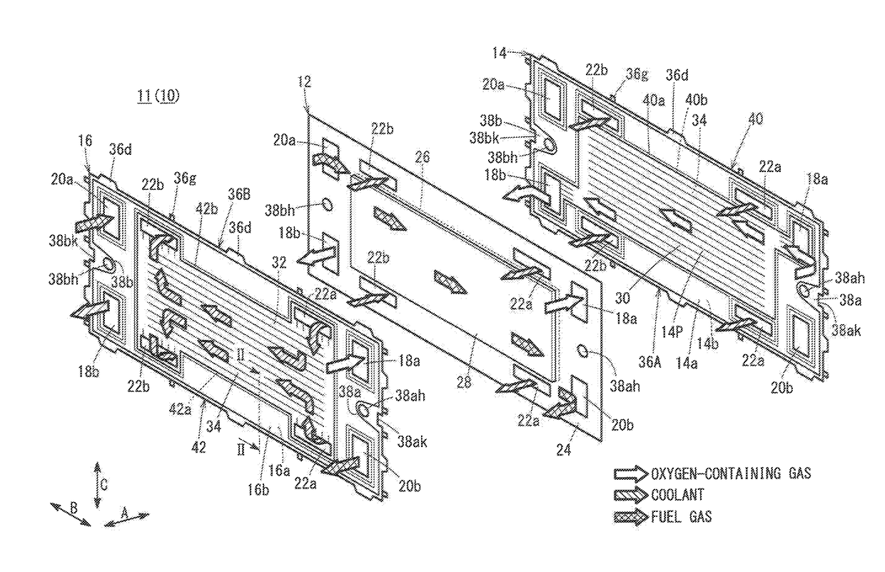
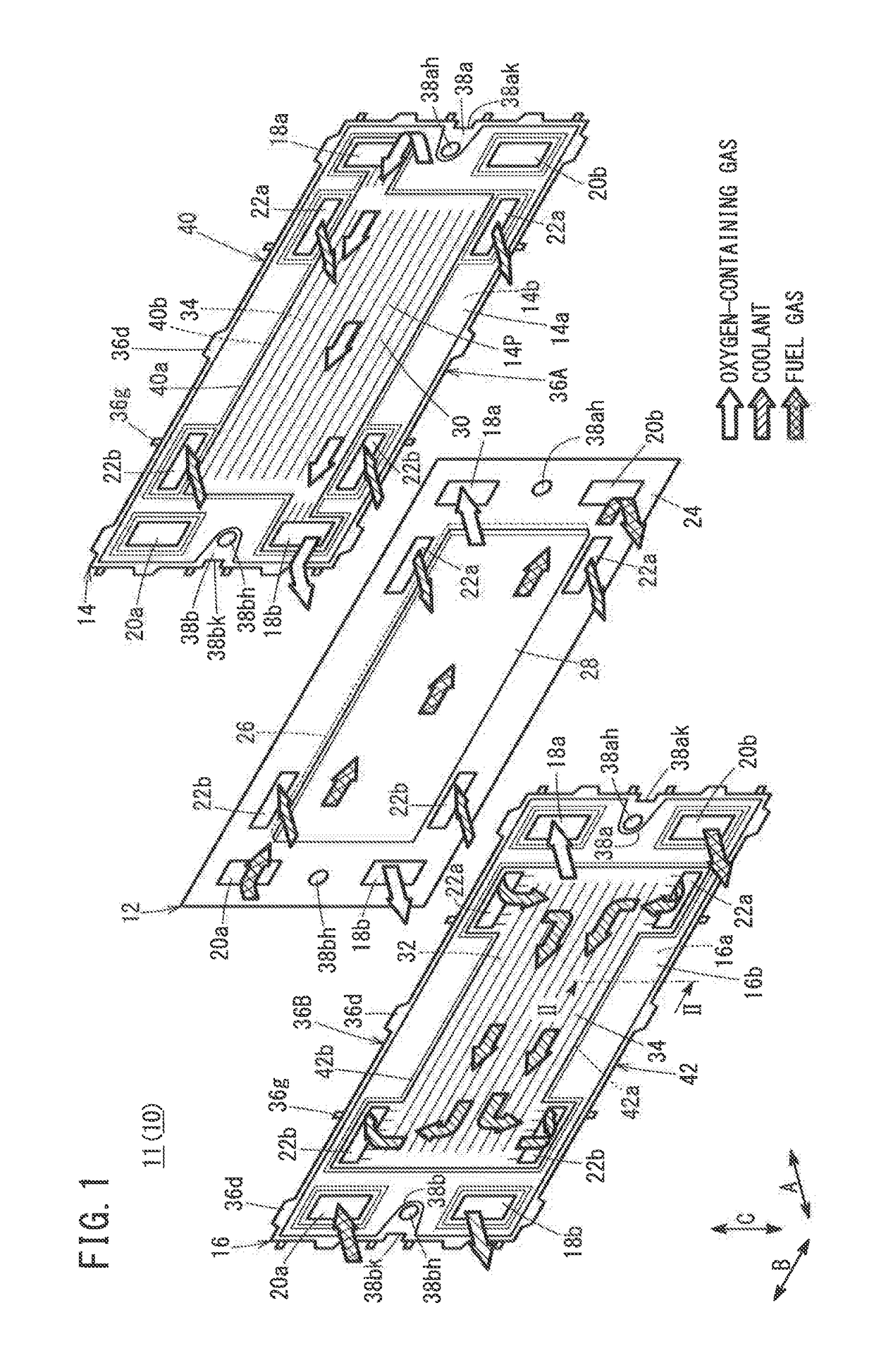
[0021]As shown in FIGS. 1 and 2, a fuel cell stack 10 including a fuel cell separator according to an embodiment of the present invention is formed by stacking laterally elongated units of fuel cells 11 (hereinafter referred to as the unit cells 11), upright (such that electrode surfaces stand vertically in parallel), in a horizontal direction indicated by an arrow A. Alternatively, longitudinally elongated unit cells 11 standing upright may be stacked together in the direction indicated by the arrow A, or lying in the horizontal direction may be stacked in the gravity direction indicated by an arrow C.

[0022]Each of the unit cells 11 includes a membrane electrode assembly 12, and a cathode side separator (fuel cell separator) 14 and an anode side separator (fuel cell separator) 16 sandwiching the membrane electrode assembly 12.

[0023]The cathode side separator 14 and the anode side separator 16 are, for example, steel plates, stainless steel plates, aluminum plates, plated steel plat...


PUM

PropertyMeasurementUnit
Thicknessaaaaaaaaaa

Abstract

A unit cell that constitutes a fuel cell stack is obtained by sandwiching an electrolyte mem-brane / electrode structure with a cathode-side separator and an anode-side separator. A first resin member is provided along the entire periphery of the cathode-side separator in the outer peripheral portion of the cathode-side separator. Surfaces of the cathode-side separator are provided with sealing parts that cover a part of the first resin member and constitute a first sealing member.

Description

TECHNICAL FIELD[0001]The present invention relates to a fuel cell separator of a fuel cell and a method of producing the fuel cell separator (separator for fuel cells and method for producing same). In the fuel cell, a membrane electrode assembly is sandwiched between separators, and seal members are formed integrally with outer ends of the separators. The membrane electrode assembly includes electrodes and an electrolyte membrane interposed between the electrodes.BACKGROUND ART[0002]For example, in a solid polymer electrolyte fuel cell, an electrolyte membrane (polymer ion exchange membrane) is interposed between an anode and a cathode to form a membrane electrode assembly (MEA). The membrane electrode assembly is sandwiched between a pair of separators to form a unit cell (power generation cell). In use, in the fuel cell, generally, a predetermined number of unit cells are stacked together to form a fuel cell stack, e.g., mounted in a fuel cell vehicle.[0003]In the fuel cell, a fu...

Claims


Application Information

Patent Timeline
IPC IPC(8): H01M8/0221H01M8/0284H01M8/1018H01M8/0267H01M8/04082
CPCH01M8/0221H01M8/0284H01M8/1018H01M8/0267H01M8/04201H01M2008/1095H01M2250/20H01M8/10H01M8/0202H01M8/0271H01M8/0206H01M8/0273H01M8/0276H01M8/0286Y02E60/50Y02T90/40
Inventor OYAMA, SATOSHIMORIMOTO, GOTERADA, SATORUGOTO, SHUHEIGIGA, AKIHITOHAYASHI, TAKAHIROMASAKA, TAKESHIYOGO, SATOMIKOGA, SHOTARO
Owner HONDA MOTOR CO LTD
Why Eureka
Try Eureka