Semiconductor device

Active Publication Date: 2018-04-05
LAPIS SEMICON CO LTD
View PDF1 Cites 1 Cited by
  • Summary
  • Abstract
  • Description
  • Claims
  • Application Information

AI Technical Summary

Benefits of technology

The patent text describes a semiconductor device that can prevent the formation of a protective film residue during production. This means that the device can be made more efficiently and with fewer defects.

Problems solved by technology

In a case in which wires are bound to the front face of the conductive film exposed in the opening of the protecting film, deficient bonding of the wire may occur, if protecting film residue adheres to the front face of the conductive film.
Further, in a case in which an external connection terminal is formed on the front face of the conductive film, deficient connection between the conductive film and the external connection terminal may occur if protecting film residue adheres to the front face of the conductive film.

Method used


Image

  • Semiconductor device
  • Semiconductor device
  • Semiconductor device

Examples


first exemplary embodiment

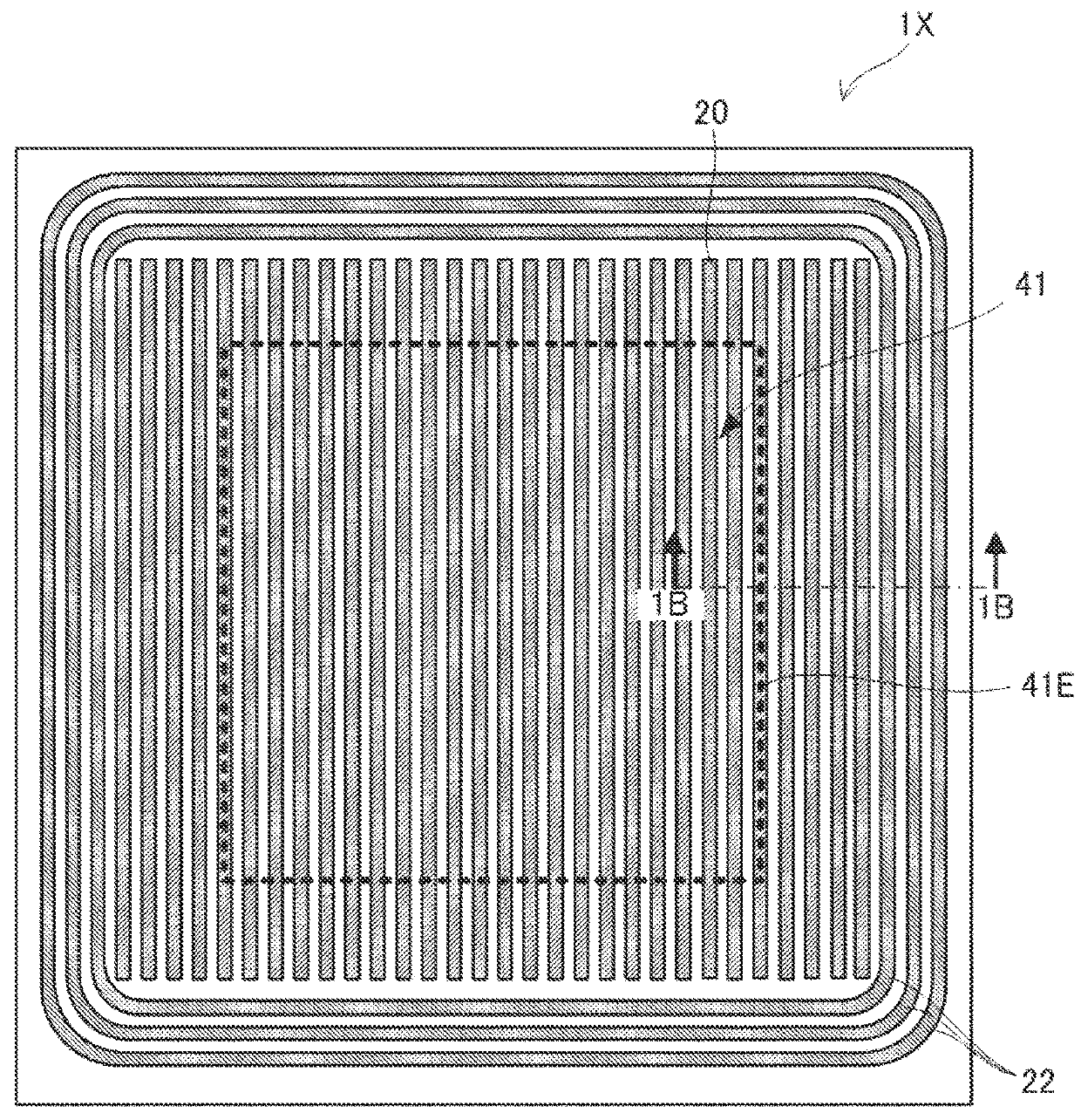
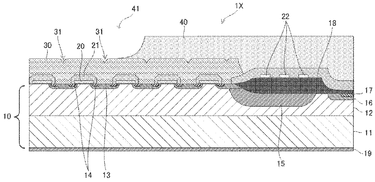
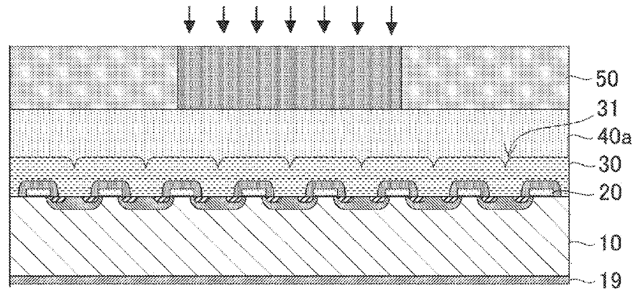
[0051]FIG. 6A is a plan view illustrating a configuration of a semiconductor device 1 according to a first exemplary embodiment of the present disclosure, and FIG. 6B is an enlarged view of a region B enclosed by the dashed line in FIG. 6A. In the semiconductor device 1, the shape of the opening 41 of the protecting film 40 differs from that in the semiconductor device 1X according to the comparative example. The configuration of the semiconductor device 1 is otherwise the same as that of the semiconductor device 1X according to the comparative example. Namely, the semiconductor device 1 configures a power MOSFET as an example, and the cross-sectional view structure thereof is the same as that of the semiconductor device 1X according to the comparative example illustrated in FIG. 1B. Further, in the semiconductor device 1, the method of forming the protecting film 40 is the same as in the semiconductor device 1X according to the comparative example. The method includes a process of ...

second exemplary embodiment

[0055]FIG. 7A is a plan view illustrating a configuration of a semiconductor device 1A according to a second exemplary embodiment of the present disclosure, and FIG. 7B is an enlarged view of a region C enclosed by the dashed line in FIG. 7A. In the semiconductor device 1A, the shape of the opening 41 of the protecting film 40 differs from that in the semiconductor device 1X according to the comparative example and the semiconductor device 1 according to the first exemplary embodiment. The configuration of the semiconductor device 1A is otherwise the same as that of the semiconductor device 1X according to the comparative example and the semiconductor device 1 according to the first exemplary embodiment. Further, in the semiconductor device 1A, the method of forming protecting film 40 is the same as that of the semiconductor device 1X according to the comparative example and the semiconductor device 1 according to the first exemplary embodiment described above. Note that although th...

third exemplary embodiment

[0059]FIG. 8A is a plan view illustrating a configuration of a semiconductor device 1B according to a third exemplary embodiment of the present disclosure, andFIG. 8B is an enlarged view of a region D enclosed by the dashed line in FIG. 8A. In the semiconductor device 1B, the shape of the opening 41 of the protecting film 40 differs from the semiconductor device 1X according to the comparative example and the semiconductor device 1 according to the first exemplary embodiment. The configuration of the semiconductor device 1B is otherwise the same as that of the semiconductor device 1X according to the comparative example and the semiconductor device 1 according to the first exemplary embodiment. Further, in the semiconductor device 1B, the method of forming the protecting film 40 is the same as in the semiconductor device 1X according to the comparative example and the semiconductor device 1 according to the first exemplary embodiment described above. Note that although the conductiv...


PUM


Abstract

The present disclosure provides a semiconductor device including: a semiconductor substrate; a conductive film covering a front face of the semiconductor substrate, a front face of the conductive film having plural straight-line shaped concave portions disposed in parallel to each other; and a protecting film covering the front face of the conductive film, the protecting film having an opening that has an edge forming an angle with the plural concave portions of greater than 0° and less than 90°, and that partially exposes the conductive film.

Description

CROSS-REFERENCE TO RELATED APPLICATION[0001]This application claims priority under 35 USC 119 from Japanese Patent Application No. 2016-196234, filed on Oct. 4, 2016, the disclosure of which is incorporated by reference herein.BACKGROUNDTechnical Field[0002]The present disclosure relates to a semiconductor device.Related Art[0003]In a semiconductor device configuring a power semiconductor device, such as a power metal-oxide-semiconductor field-effect transistor (MOSFET) or an insulated gate bipolar transistor (IGBT), a protecting film configured by an insulator such as polyimide is provided on the outermost face of the semiconductor device.[0004]As technology related to patterning of polyimide films that function as protecting films, for example, Japanese Patent Application Laid-Open (JP-A) No. H09-129589 discloses a polyimide film patterning method including: forming a polyimide film on a substrate, forming a resist film on the polyimide film; forming a resist pattern by developing...

Claims


Application Information

Patent Timeline
IPC IPC(8): H01L29/423H01L23/31H01L29/78H01L29/739
CPCH01L29/4238H01L23/3157H01L29/7802H01L29/7395G03F7/16G03F7/2022G03F7/42H01L21/027H01L29/66477H01L29/78H01L2224/0382H01L24/03H01L24/05H01L2224/02166H01L2224/05558H01L2924/13055H01L2924/13091H01L29/404H01L29/417H01L29/0619H01L29/0638H01L29/41741H01L29/7811H01L29/0615
Inventor YONEKURA, TOMOKO
Owner LAPIS SEMICON CO LTD
Why Eureka
Try Eureka