Cutting method and tool path generating device

Active Publication Date: 2017-01-12
MAKINO MILLING MASCH CO LTD
View PDF3 Cites 0 Cited by
  • Summary
  • Abstract
  • Description
  • Claims
  • Application Information

AI Technical Summary

Benefits of technology

This patent text describes a method for machining workpieces to prevent the production of burrs. The method includes generating a tool path to remove burrs from the workpiece. By using this tool path, operators can remove burrs more efficiently, reducing the amount of time it takes to machine the workpiece and increasing productivity. Additionally, the method includes setting an area where the corner is formed and generating a tool path that deviates from the original path in areas outside of the corner. Overall, this patent provides a cutting method that prevents burrs from being left when machining workpieces.

Problems solved by technology

The aforementioned Japanese Laid-open Patent Publication No. 2013-151030A does not disclose a method for effectively removing a burr produced on a corner of a workpiece.
However, the operator will have an increased workload to prolong the time for machining the workpiece, and thus the productivity of workpieces will be reduced.
In particular, for machining a workpiece to make a target shape having a lot of corners, it takes a long time due to the need for removing burrs produced on the individual corners.
However, this method is still problematic in that the time period for machining workpieces is extended.

Method used


Image

  • Cutting method and tool path generating device
  • Cutting method and tool path generating device
  • Cutting method and tool path generating device

Examples


Embodiment Construction

[0029]A cutting method and a tool path generation device according to an embodiment will now be described with reference to FIGS. 1 to 10. The machining according to the present embodiment is a cutting operation for machining a workpiece into a desired shape by cutting off part of the workpiece. The cutting of the workpiece can be performed with a numerical control type machine tool.

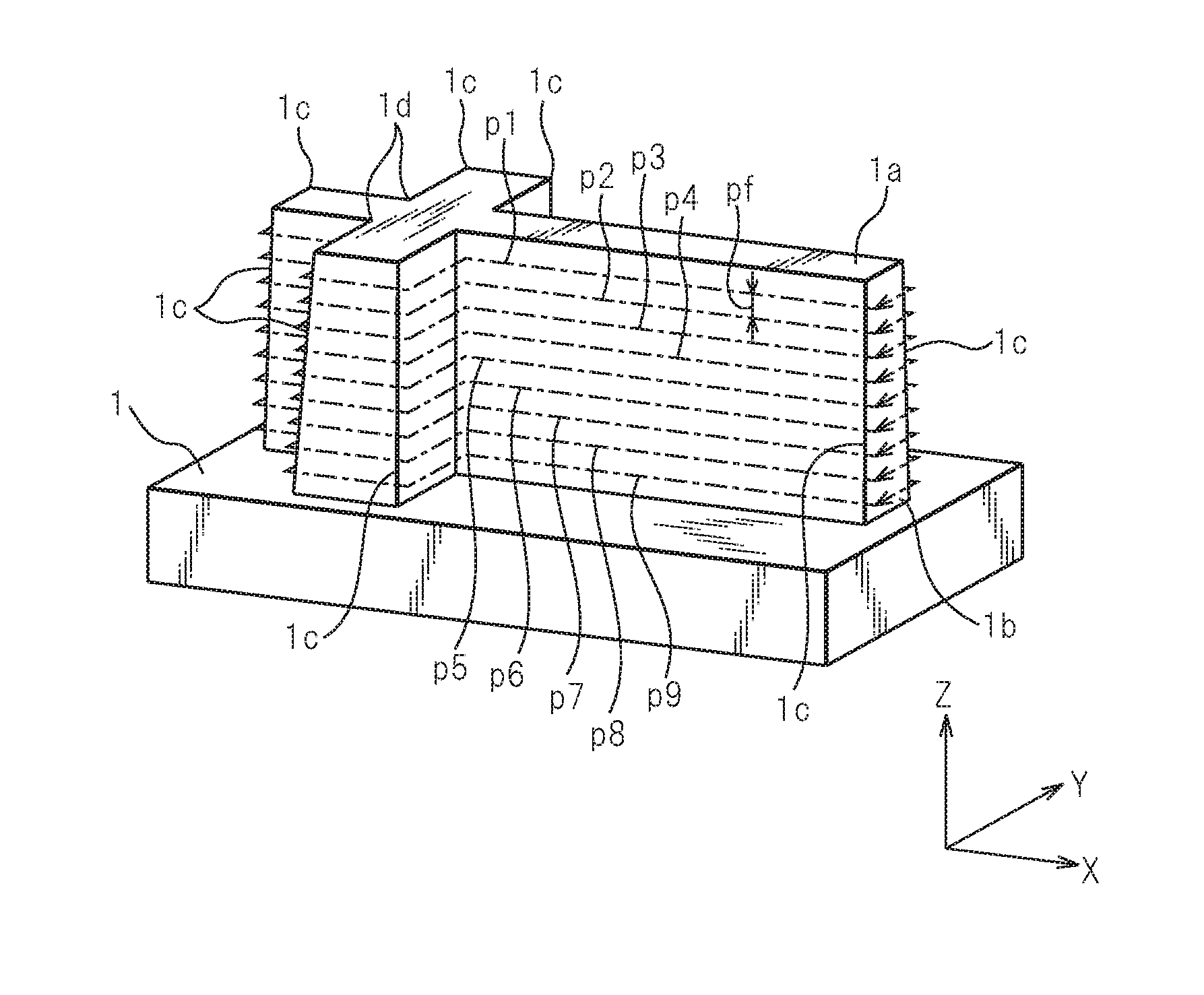
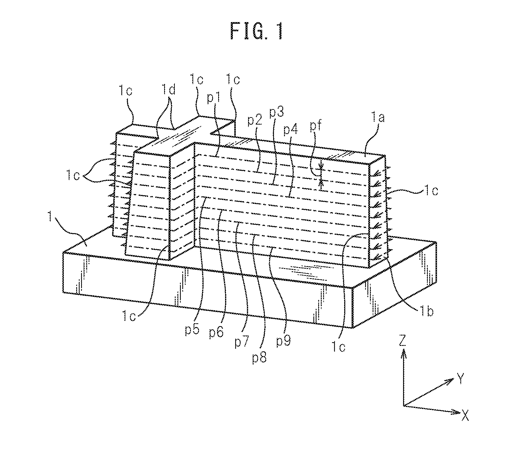
[0030]FIG. 1 is a schematic perspective view of the workpiece which has been machined into the target shape by using a first cutting method according to an embodiment. According to the first cutting method, sides of the cuboidal workpiece 1 are cut to form the workpiece 1 into a cross shape on its plane.

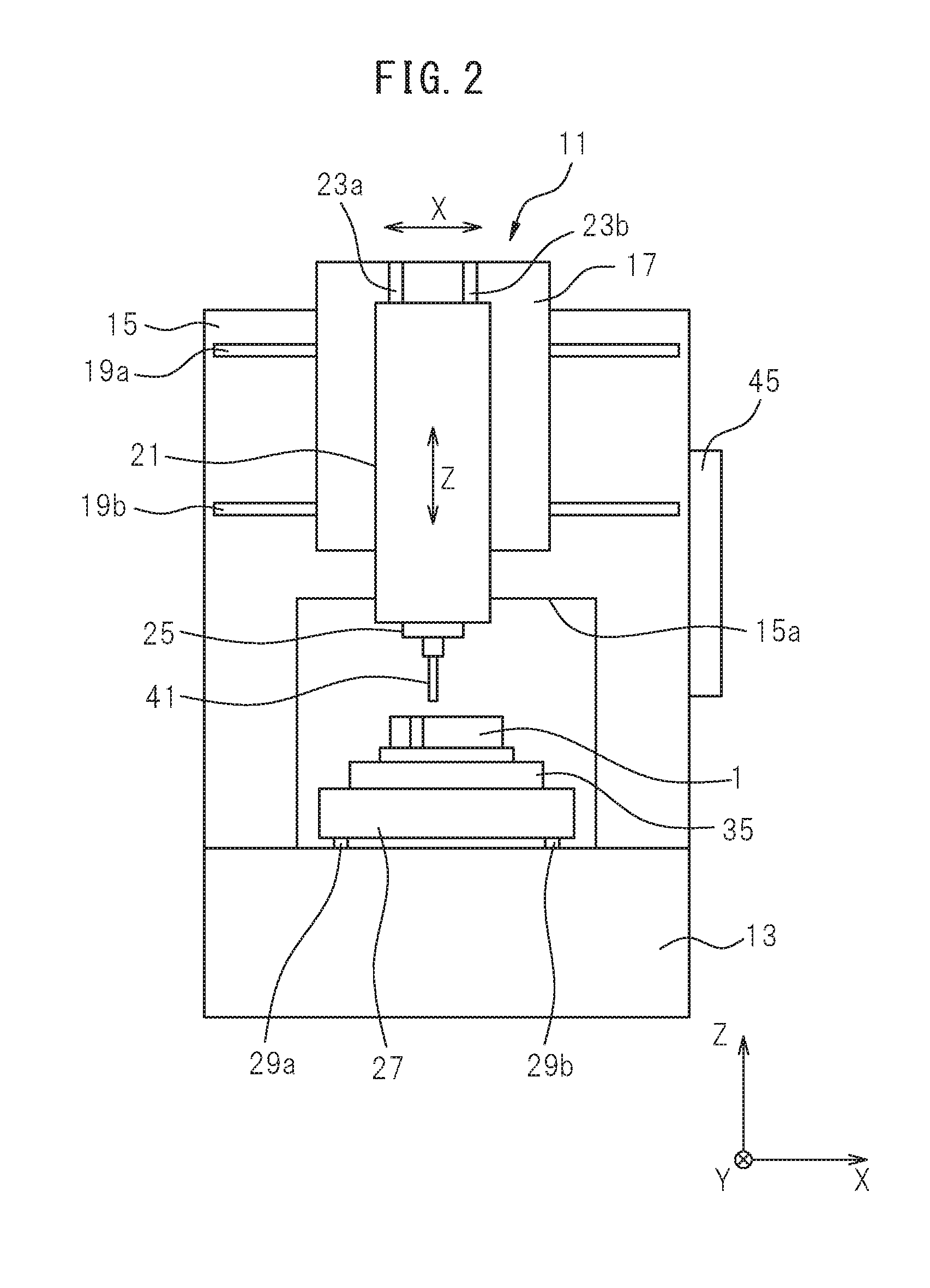
[0031]FIG. 2 is a schematic front view of a machine tool according to the present embodiment. The machine tool 11 includes a bed 13 serving as a base table and a column 15 vertically disposed on the top surface of the bed 13. A carriage 27 is disposed on top of the bed 13. On the top surface of the carria...


PUM


Abstract

A cutting method in which a workpiece is cut on the basis of a plurality of tool paths parallel to one another into a shape having a corner that protrudes outward. A machining step for machining the workpiece on the basis of one tool path and a moving step for moving to the starting point of the next machining step after the completion of the one machining step are repeated. In the machining step, a cutting step for cutting the workpiece in the one tool path and a removing step for removing a burr by moving a tool relatively to the workpiece in the same tool path as that of the cutting step in a region forming the corner are successively performed.

Description

CROSS-REFERENCE TO RELATED APPLICATIONS[0001]This application is a U.S. National Stage patent application of International Patent Application No. PCT / JP2014 / 051834, filed Jan. 28, 2014, which is hereby incorporated by reference in the present disclosure in its entirety.FIELD OF THE INVENTION[0002]The present invention relates to a cutting method and a tool path generation device.BACKGROUND OF THE INVENTION[0003]In conventional techniques, a machine tool which rotates a rotating tool to machine a workpiece is known. Among such machine tools, a numerical control type machine tool which specifies a path of the rotating tool by using coordinates on predetermined axes or the like, and machines a workpiece while automatically making relative movements of the rotating tool with respect to the workpiece is known. Such machine tool can perform the cutting operation on a workpiece by using a milling cutter tool as the tool.[0004]When a workpiece is cut, a small projection on a machined surfac...

Claims


Application Information

Patent Timeline
IPC IPC(8): G05B19/29B23C3/12G05B19/4093
CPCG05B19/29G05B19/40937B23C2220/20G05B2219/45151G05B2219/49392B23C3/12Y02P90/02B23Q15/013
Inventor MASUMIYA, YASUNORISUZUKI, KYOHEIYABE, KAZUTOSHIKAGEYAMA, TAKASHI
Owner MAKINO MILLING MASCH CO LTD
Why Eureka
Try Eureka