Frame and image forming apparatus using the frame

Active Publication Date: 2009-11-05
RICOH KK
View PDF15 Cites 19 Cited by
  • Summary
  • Abstract
  • Description
  • Claims
  • Application Information

AI Technical Summary

Problems solved by technology

However, for various reasons, some image forming apparatuses may be installed on a surface that is not flat or level, which may strain or distort the frame of the apparatus.
Such strain on or distortion of the frame may cause strain on or distortion of the image forming unit supported by the frame, which in turn may result in image quality deterioration.
For example, a driving unit, a power unit or the like may be disposed at the rear side of apparatus, and thus not easily accessible by a user.
A further complication is that, to reduce a footprint of the image forming apparatus, such units disposed at the rear side of apparatus may be projected rearward outside of the footprint of apparatus.
When an image forming apparatus having a center of gravity at its rearward portion is installed on an uneven surface, the image forming apparatus may be unstable.
Consequently, strain or distortion may be more likely to occur at the front side of the frame of image forming apparatus.
In such a frame, the front plate may not have a good level of stiffness because some open space is required for withdrawing a sheet cassette from the sheet feed unit.
But the support pillars may not be extended to the base plate or a portion supporting the sheet feed unit.
Accordingly, such configuration may not effectively enhance stiffness of the frame at the front side.
Consequently, strain on or distortion of the image forming unit may occur due to a lack of stiffness of the frame.
A greater front plate may have a lower precision on its physical dimensions, and may increase manufacturing cost, die or molding cost, and delivery cost, by which cost reduction may be hard to attain.
Further, hollow supports need a welding process for closing a gap of support pillar.
Further, the support pillar may need a welding process and a joint member for fixing the support pillars, by which a manufacturing cost may increase compared to a support pillar having a U-shaped form.
Further, such frame may need a plurality of front and rear plates, by which cost reduction may be hard to attain.

Method used


Image

  • Frame and image forming apparatus using the frame
  • Frame and image forming apparatus using the frame
  • Frame and image forming apparatus using the frame

Examples


Embodiment Construction

[0031]A description is now given of example embodiments of the present invention. It should be noted that although such terms as first, second, etc. may be used herein to describe various elements, components, regions, layers and / or sections, it should be understood that such elements, components, regions, layers and / or sections are not limited thereby because such terms are relative, that is, used only to distinguish one element, component, region, layer or section from another region; layer or section. Thus, for example, a first element, component, region, layer or section discussed below could be termed a second element, component, region, layer or section without departing from the teachings of the present invention.

[0032]In addition, it should be noted that the terminology used herein is for the purpose of describing particular embodiments only and is not intended to be limiting of the present invention. Thus, for example, as used herein, the singular forms “a”, “an” and “the” ...


PUM


Abstract

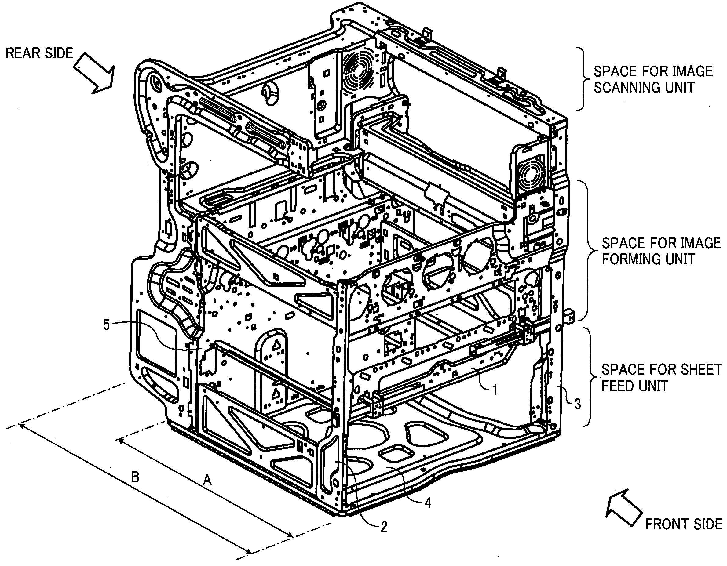
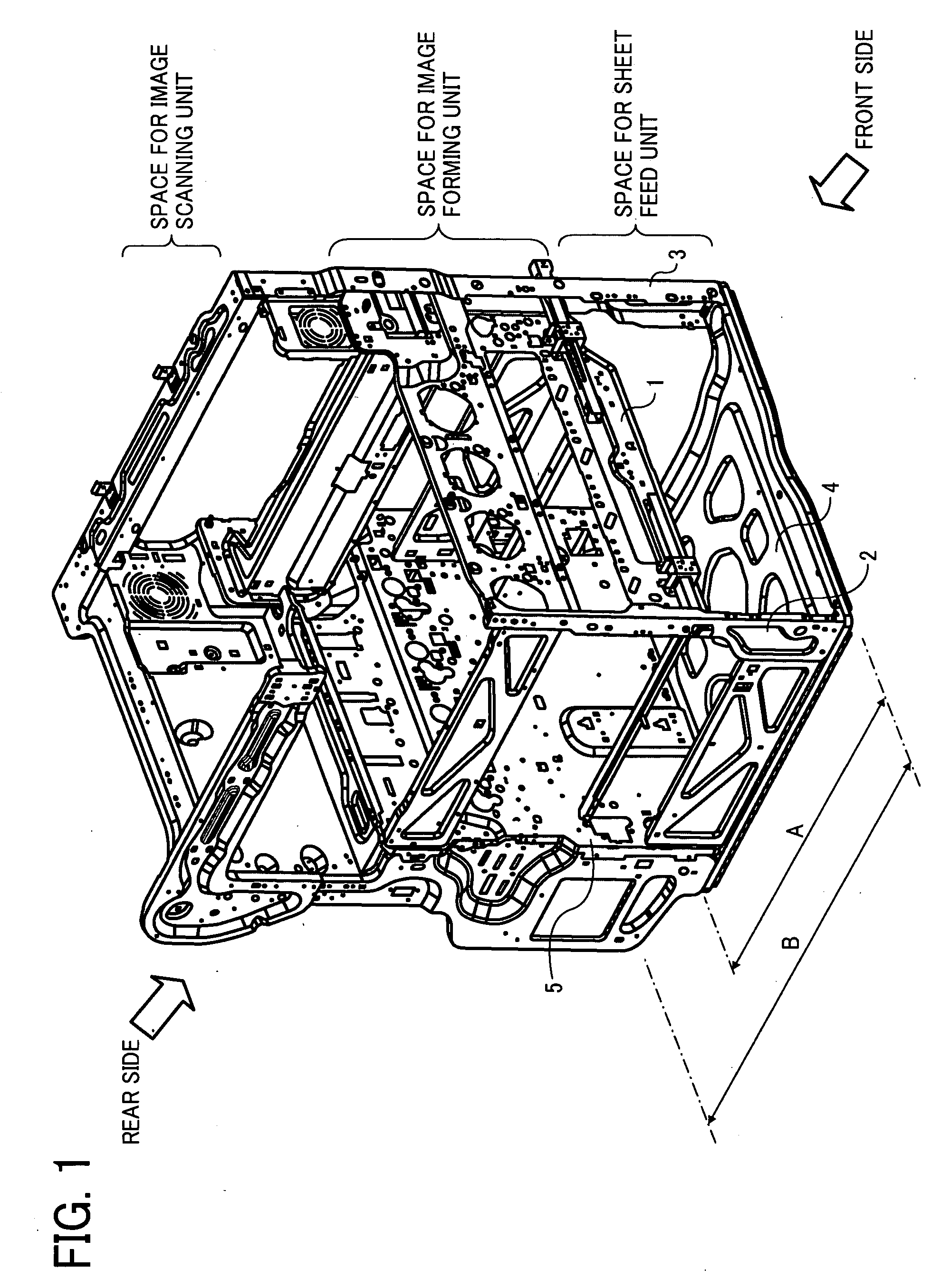
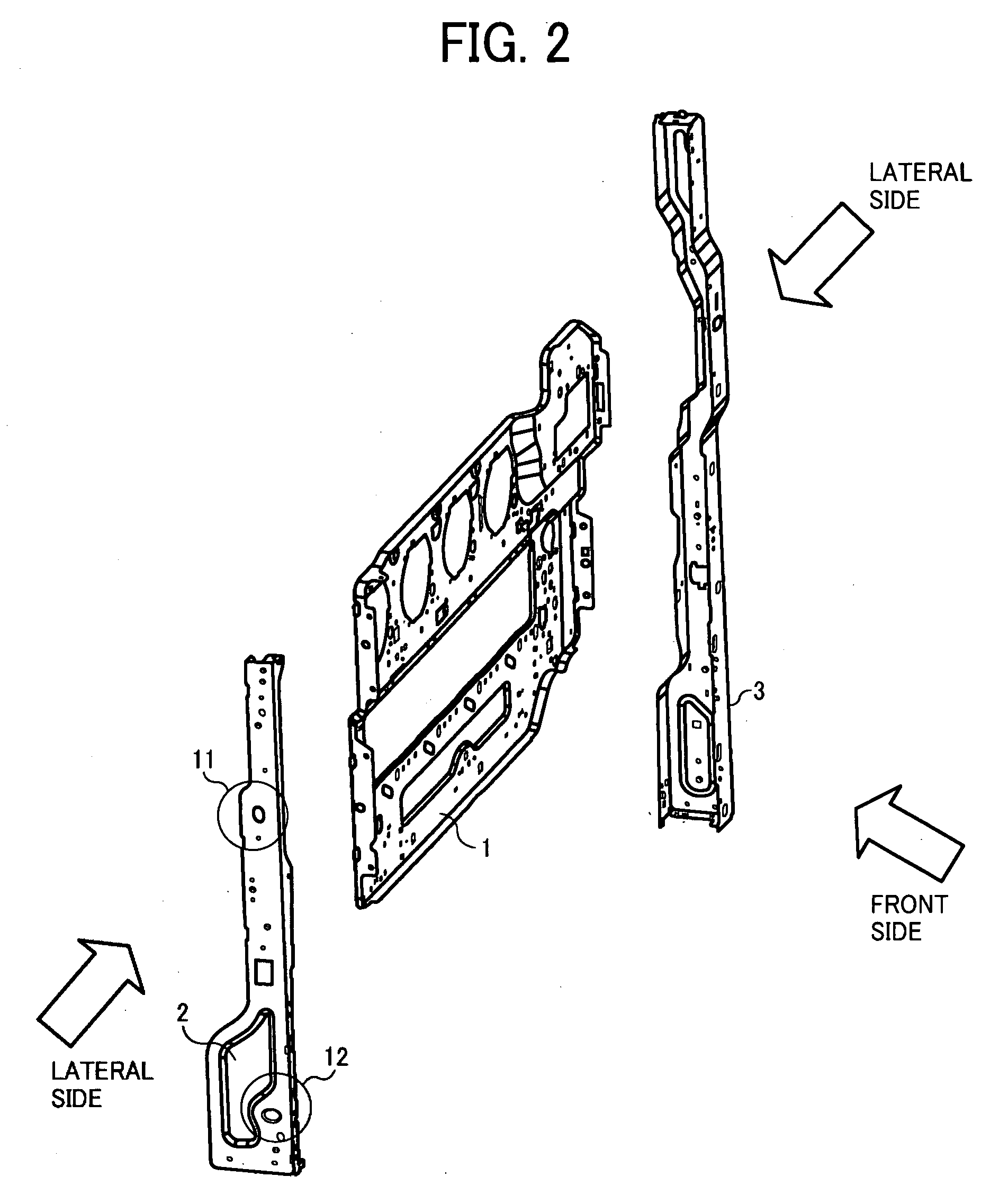
A frame for an image forming apparatus including at least one functional unit includes a front member, a rear member, a base member, and a pair of elevated supporters. The front and rear members at least support the functional unit. The base member supports at least the rear member. The pair of elevated supporters, fixed at least to the base member, have a U-shaped form in its cross-section. The elevated supporters are spaced a given distance apart and disposed facing an open part of the U-shaped form of the pair of elevated supporters. The elevated supporters supports both lateral rim portions of the front member at a given position of the pair of elevated supporters. The front member is indirectly fixed with the base member via the elevated supporters, and positions the functional unit at a given position.

Description

CROSS-REFERENCE TO RELATED APPLICATIONS[0001]This application claims priority under 35 U.S.C. 119(a) to Japanese Patent Application No. 2008-118054, filed on Apr. 30, 2008 in the Japan Patent Office, the entire contents of which are hereby incorporated by reference herein.BACKGROUND OF THE INVENTION[0002]1. Field of the Invention[0003]The present disclosure generally relates to a frame of an image forming apparatus such as a copier, a printer, a facsimile machine, or the like, and an image forming apparatus using the frame.[0004]2. Description of the Background Art[0005]Typically, image forming apparatuses employ a frame to define the apparatus, allow access to the interior of the apparatus, and support functional units inside the apparatus at precise positions within the apparatus, wherein the functional units may include an image forming unit but not limited to thereto. The frame supports the functional units either by direct contact or indirectly.[0006]Ideally, the image forming ...

Claims


Application Information

Patent Timeline
IPC IPC(8): G03G15/00
CPCG03G2221/1678G03G21/16
Inventor TAKEMOTO, HIDEYUKI
Owner RICOH KK
Why Eureka
Try Eureka