Thermoelectric generator

a generator and thermal energy technology, applied in the field of thermal energy modules, can solve the problems of small power requirements in comparison with the power requirements of a typical hom

Inactive Publication Date: 2009-12-10
WATTS THERMOELECTRIC
View PDF24 Cites 44 Cited by
  • Summary
  • Abstract
  • Description
  • Claims
  • Application Information

AI Technical Summary

Benefits of technology

[0007]In some embodiments, the thermoelectric generator further comprises one or more flexible tubes, at least one of the tubes connecting each of the manifolds with each of its respective first or second thermal elements. At least one of the flexible tubes may be press fit into its respective manifold and thermal element. The first fluid may be water. The second fluid may be water.
[0008]In another embodiment, a method of fabricating a thermoelectric generator for generating electrical power from a difference in temperature comprises providing a plurality of thermoelectric modules, each thermoelectric module having a first side and a second side, and each thermoelectric module generating electrical power when subjected to a temperature differential between its respective first side and second side. The method further comprises providing a plurality of first thermal elements configured to receive heat from a first fluid, and providing a plurality of second thermal elements configured to be cooled by a second fluid. The first and second thermal elements are arranged in a stack of alternating first and second thermal elements having one of the thermoelectric modules between each adjacent pair of first and second thermal elements. Each thermoelectric module is in contact on its first side with

Problems solved by technology

For example, a typical commercially available thermoelectric module about 34×31 millimeters may produce about 1.5 watts of power at about 2.8 volts when subjected to a temper

Method used


Image

  • Thermoelectric generator
  • Thermoelectric generator
  • Thermoelectric generator

Examples


Embodiment Construction

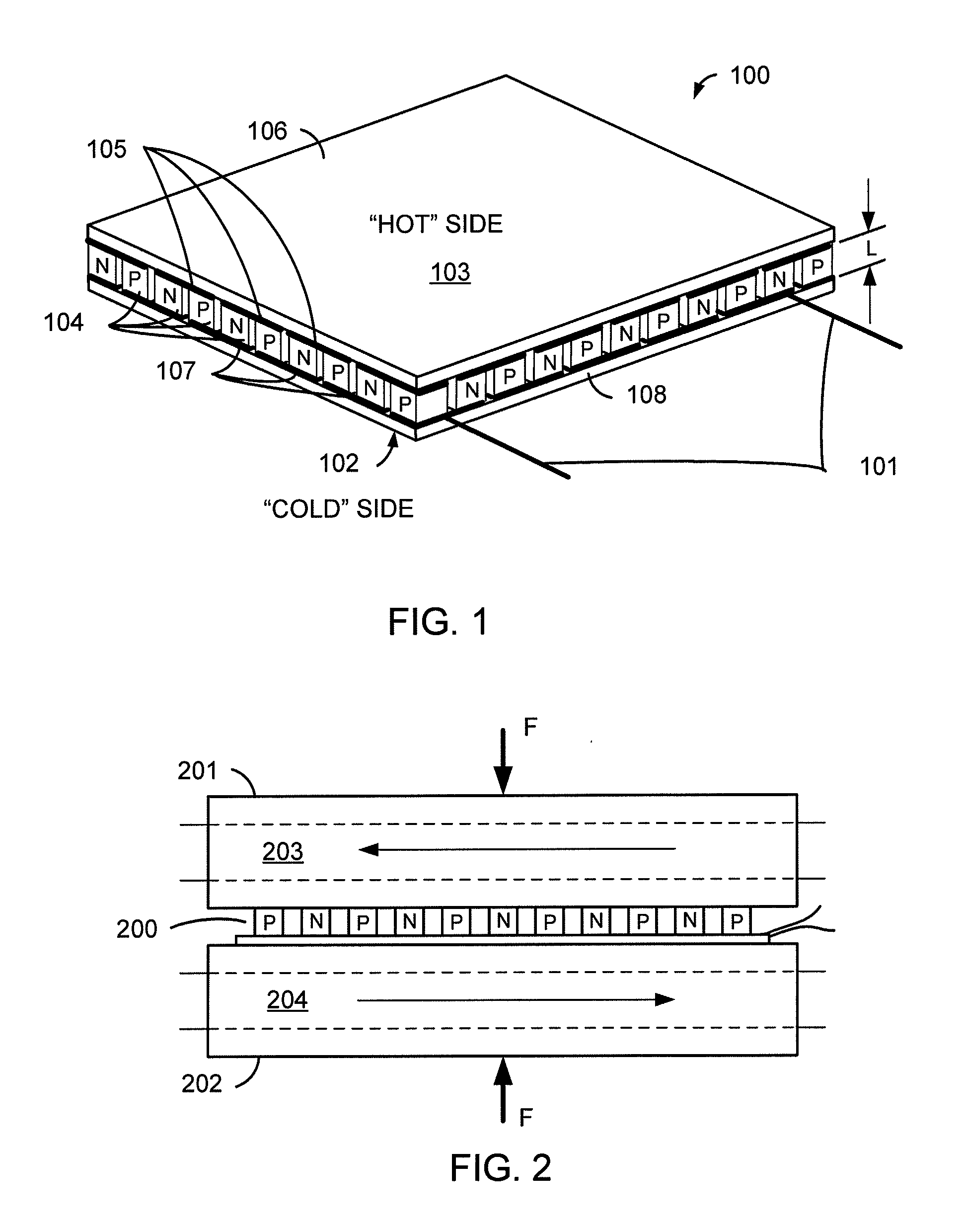
[0023]Thermoelectric module 100 is but one example of a thermoelectric device usable by embodiments of the invention. Module 100 is made up of a number of thermoelectric elements 104, each of which is a length of conductive or semiconductive material with favorable thermoelectric properties. For example, the elements may be pieces of n-type and p-type semiconductor material, labeled “N” and “P” in FIG. 1. The thermoelectric elements 104 are arranged in thermoelectric couples, each thermoelectric couple including one “N” element and one “P” element. The ends of the elements in each thermoelectric couple are electrically connected at hot side 103 of module 100 by one of conductors 105, and are further thermally connected to a heat source through an optional header 106. The various thermoelectric couples are connected in series at cold side 102 of module 100, by conductors 107, and are also thermally connected to a “cold” source or header 108 at the cold side 103 of module 100. Each th...


PUM

PropertyMeasurementUnit
Temperatureaaaaaaaaaa
Flexibilityaaaaaaaaaa

Abstract

A thermoelectric generator includes a plurality of thermoelectric modules that generate electrical power when subjected to a temperature differential. The generator also includes a plurality of first thermal elements to which heat is supplied by a first fluid and a plurality of second thermal elements from which heat is removed by a second fluid. The first and second thermal elements are arranged in a stack of alternating first and second thermal elements having one of the plurality of thermoelectric modules between each adjacent pair of first and second thermal elements. Each thermoelectric module is in contact on its first side with one of the first thermal elements and in contact on its second side with one of the second thermal elements such that no face of any thermal element contacts more than one of the thermoelectric modules.

Description

[0001]This application claims priority to U.S. provisional application 61 / 060,377, filed Jun. 10, 2008 and titled “Combined Heat and Power and Hydrogen Generation for Whole Home or Building with Ground Heat Exchanger Using Thermoelectric Seebeck Modules”, the disclosure of which is hereby incorporated herein in its entirety for all purposes.CROSS REFERENCE TO RELATED APPLICATIONS[0002]This application is related to U.S. patent application Ser. No. ______ (Attorney docket number 027483-000210US), titled “Integrated Energy System for Whole Home or Building”, and to U.S. patent application Ser. No. ______ (Attorney docket number 027483-000300US), titled “Automatic Configuration of Thermoelectric Generation System to Load Requirements”, both having the same inventor as the present application and filed Jun. 10, 2009. The disclosures of those two applications are hereby incorporated herein in their entirety for all purposes.BACKGROUND OF THE INVENTION[0003]A thermoelectric module is a de...

Claims


Application Information

Patent Timeline
IPC IPC(8): H01L35/02H01L35/34F24S90/00
CPCH01L35/00Y02B10/20F24J2/42H01L35/30Y02E10/40Y10T29/49002F24S90/00H10N10/00H10N10/13
Inventor WATTS, PHILLIP C.
Owner WATTS THERMOELECTRIC
Why Eureka
Try Eureka