Lamp with a base at one end

a technology of a base and a lamp body, which is applied in the direction of lamp incadescent bodies, vacuum tubes/containers/shields, electric discharge lamps, etc., can solve the problem that the dimensions of the reflector's neck must be matched to the standard dimensions of the base, and achieve the effect of simple holder, reliable and cost-effective solution

Inactive Publication Date: 2009-12-10
LEDVANCE GMBH
View PDF3 Cites 0 Cited by
  • Summary
  • Abstract
  • Description
  • Claims
  • Application Information

AI Technical Summary

Benefits of technology

[0019]A simple, reliable and cost-effective solution for the holder of the enveloping part consists of the clamping part comprising clamps distributed around the circumference or an enveloping clamping band. In particular, the clamping band is a deformable ring which is produced out of metal or plastics in particular, so that a very simple holder is made possible by the clamping band first of all already being bent at the lower edge and it being pulled up over the base insulator to the projecting segment on impact. As soon as the enveloping part is placed, it is possible for the ring, preferably composed of aluminum, to be mechanically formed onto the segment and hence to be fixed to the edge of the enveloping part.
[0020]The prior art discloses inserting a damping means between the clamping part and the upper contact face of the edge of the enveloping part. In particular, this damping means is a type of O-ring, for example consisting of an elastomer. The material of the enveloping part, advantageously glass or aluminum, is protected from damage by said means during the forming process.

Problems solved by technology

One disadvantage of this is the fact that the dimensions of the neck of the reflector must be matched to the standard dimensions of the base.

Method used


Image

  • Lamp with a base at one end
  • Lamp with a base at one end
  • Lamp with a base at one end

Examples


first embodiment

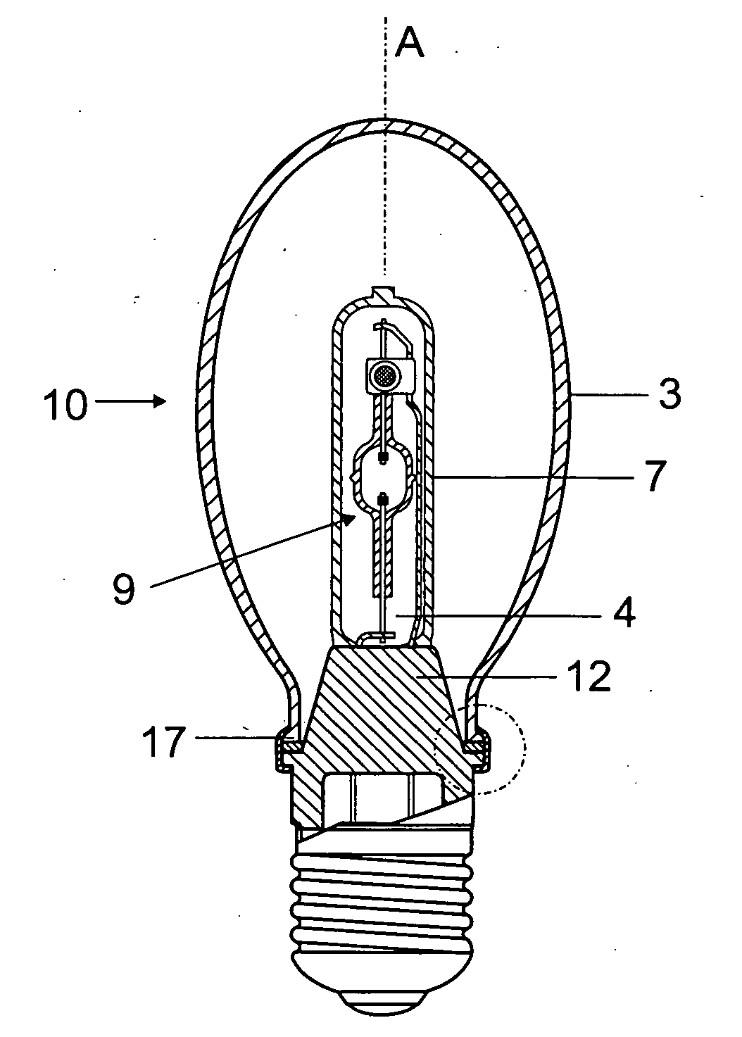
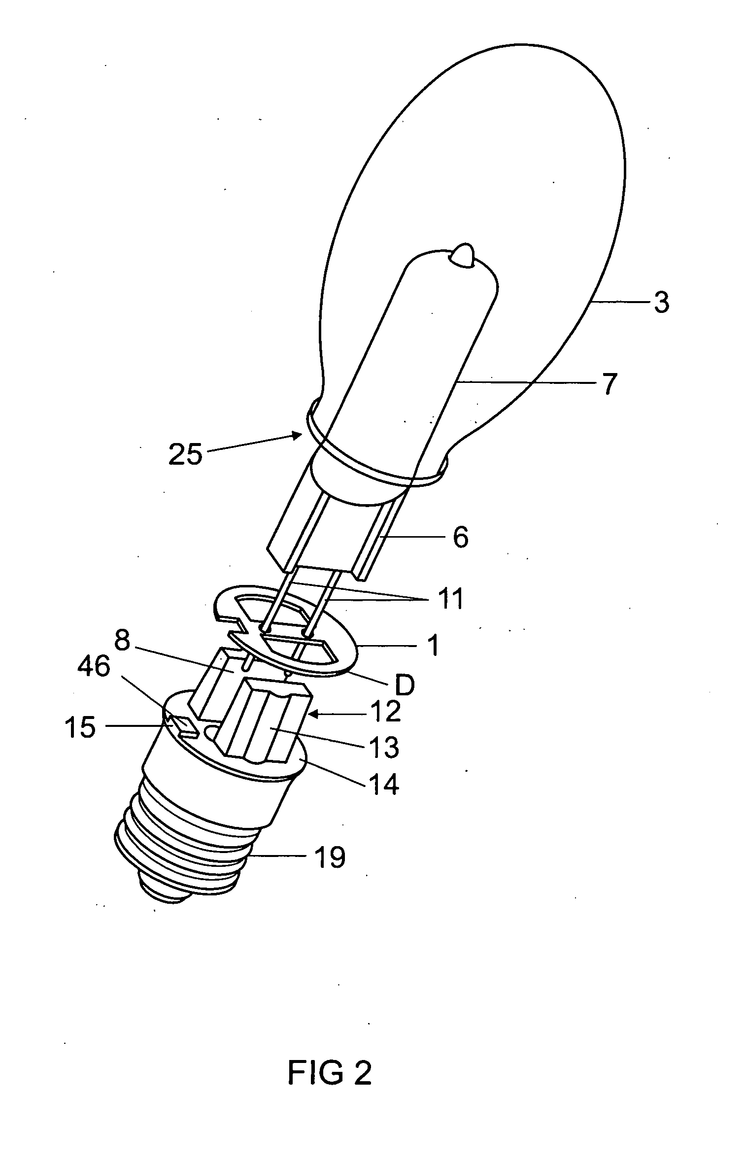
[0014]In particular, in a first embodiment, the enveloping part is attached by a clamping part bridging, in a holding fashion, the distance between the lower plateau of the base insulator and at least the upper contact face of the edge.

second embodiment

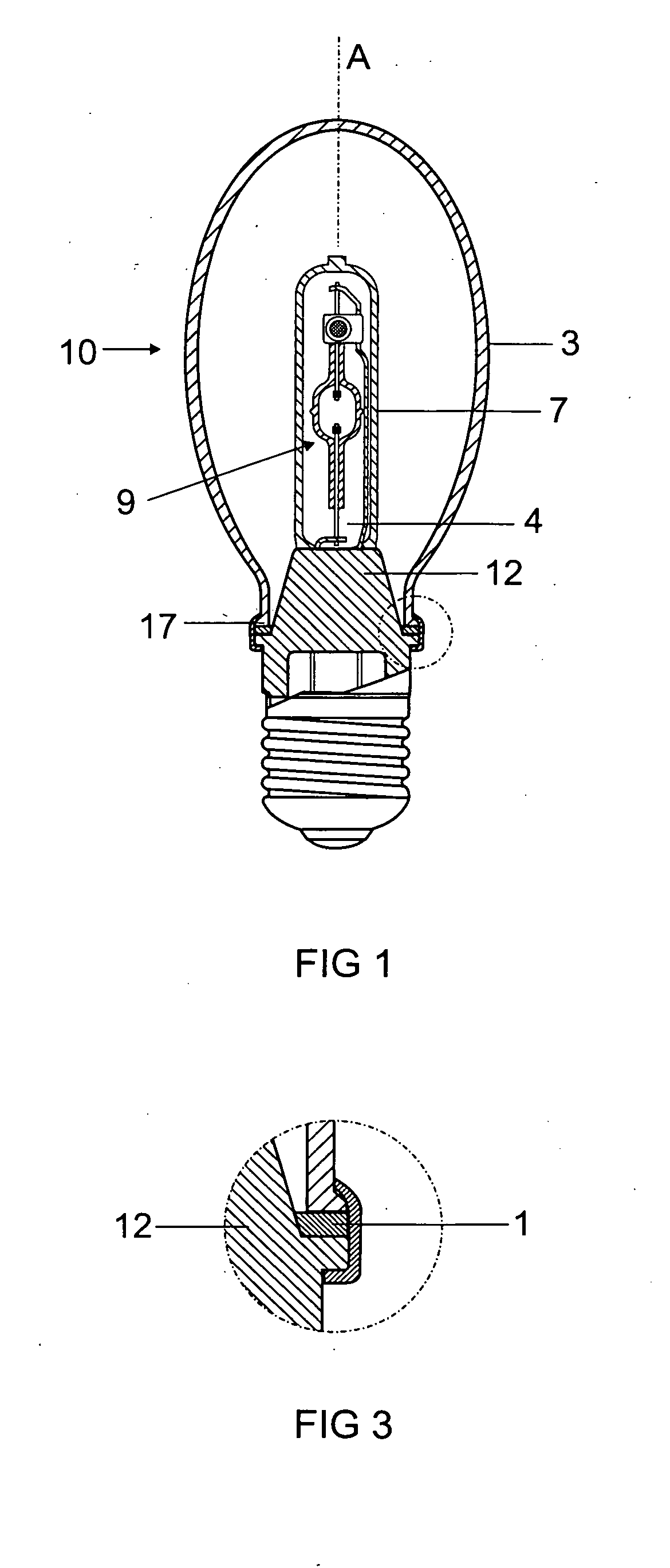
[0015]Without limiting the invention, the enveloping part and the clamping part can form a unit in a second embodiment, with the holder of the enveloping part being implemented in the upper part of the base insulator, for example by crimping.

[0016]In addition to the base insulator, the base has a conventional part facing the lamp holder, for example a screw-type base attachment or a bayonet-type base attachment.

[0017]The lamp bulb, that is so say e.g. the outer bulb or the discharge vessel if there is no outer bulb, is preferably held in the central opening by means of a spring clip. In principle, this technique is known, see DE 198 56 871, for example.

[0018]In particular, the edge of the enveloping part and the segment of the base insulator are provided with an interacting anti-twist mechanism.

[0019]A simple, reliable and cost-effective solution for the holder of the enveloping part consists of the clamping part comprising clamps distributed around the circumference or an envelopin...


PUM


Abstract

A lamp with a base at one end, in particular a high-pressure lamp, with a light bulb sealed in a vacuum-tight fashion, with the latter being surrounded by an outer bulb and an enveloping part, with a base supporting firstly the outer bulb and secondly the enveloping part, having the following features:
  • a) the base has a base insulator which is produced from an insulating material and has a central opening which holds the outer bulb;
  • b) the base insulator has a circular segment with a plateau;
  • c) the enveloping part has a circular opening with a radially projecting edge which has a lower and upper contact face relative to the base on the base side, the lower contact face of the edge fitting together with the upper plateau of the circular, radially projecting segment on the base insulator;
  • d) the enveloping part is attached to the base insulator by a cement-free mechanical holding mechanism, with an annular damping element being inserted between enveloping bulb and base insulator.

Description

TECHNICAL FIELD[0001]The invention relates to a lamp with a base at one end in accordance with the preamble of claim 1. These are in particular high-pressure discharge lamps, preferably metal-halide lamps, but also halogen incandescent lamps, for example. In this case, use is frequently made of an elongate, in particular ceramic, discharge vessel as a lamp bulb.PRIOR ART[0002]DE-C1 43 17 252 has already disclosed a lamp with a base at one end which comprises three bulbs. It has a ceramic adapter which is fitted to a screw-type base. Atmospheric pressure prevails between the enveloping bulb and the outer bulb.[0003]EP 1 109 199 describes a high-pressure lamp with a base at one end, in which the outer bulb is surrounded by a reflector. The base is fastened directly to the reflector neck by means of crimping. One disadvantage of this is the fact that the dimensions of the neck of the reflector must be matched to the standard dimensions of the base.[0004]WO2005015605 discloses a lamp wi...

Claims


Application Information

Patent Timeline
Patent Type & Authority Applications(United States)
IPC IPC(8): H01J5/00
CPCH01J61/34H01J5/60
Inventor ARNDT, JOACHIMFIDLER, UWE
Owner LEDVANCE GMBH
Why Eureka
Try Eureka