Partially reusable surgical stapler

a stapler and part-reusable technology, applied in the field of surgical staplers, can solve the problems of difficult sterilization after use, relatively complicated mechanical instruments with reusable staplers, etc., and achieve the effect of convenient replacement, convenient replacement and convenient replacemen

Inactive Publication Date: 2009-12-17
CILAG GMBH INT +1
View PDF38 Cites 1614 Cited by
  • Summary
  • Abstract
  • Description
  • Claims
  • Application Information

AI Technical Summary

Benefits of technology

[0005]In accordance with the present invention, a partially reusable surgical stapler is provided for deploying staples into tissue. The stapler has a body with a distal end, a proximal end and a longitudinal axis therebetween. The proximal end includes a handle while the distal end includes a staple cartridge holder and an opposing anvil. The stapler also has an actuator module for deploying staples. The actuator module includes at least one longitudinally movable member for sequentially ejecting staples towards the anvil. The actuator module is readily removable and replaceable to and from the body.
[0006]In another embodiment, the present invention provides a partially reusable surgical stapler having an upper jaw member with a proximal handle end and a distal anvil end. A lower jaw member having a proximal channel-shaped frame and a distal staple cartridge channel is aligned with the upper jaw. An actuator module, having at least one longitudinally moveable member for sequentially ejecting staples towards the anvil, is readily removable and replaceable to and from the lower jaw frame. A staple cartridge containing a plurality of staples is removably disposed within the staple cartridge channel. A latching member for connecting the upper and lower jaws together is provided at an intermediate position along a longitudinal axis of the stapler. The latching member is moveable relative to the upper and lower jaw members to place the stapler in a series of different locking states. The different locking states include an assembly state for connecting and disconnecting the latching member to the jaw members, and a closed, latched state in which the latching member is locked to the jaw members.

Problems solved by technology

Reusable staplers have typically been relatively complicated mechanical instruments which are difficult to sterilize after use.

Method used


Image

  • Partially reusable surgical stapler
  • Partially reusable surgical stapler
  • Partially reusable surgical stapler

Examples


Embodiment Construction

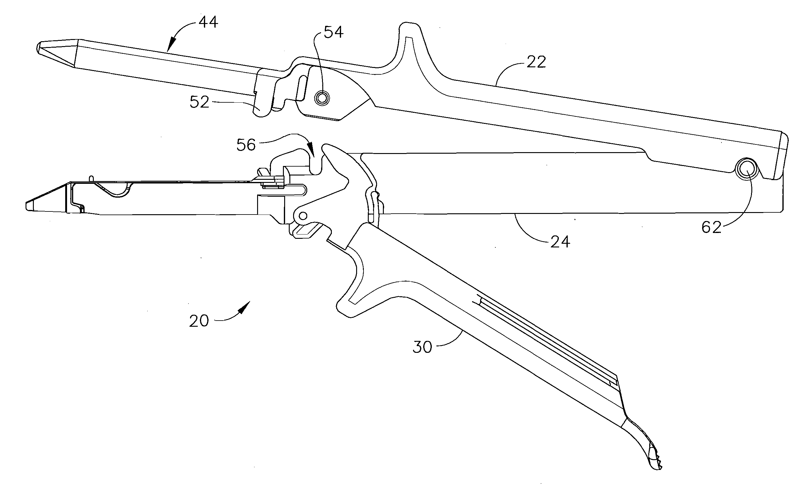
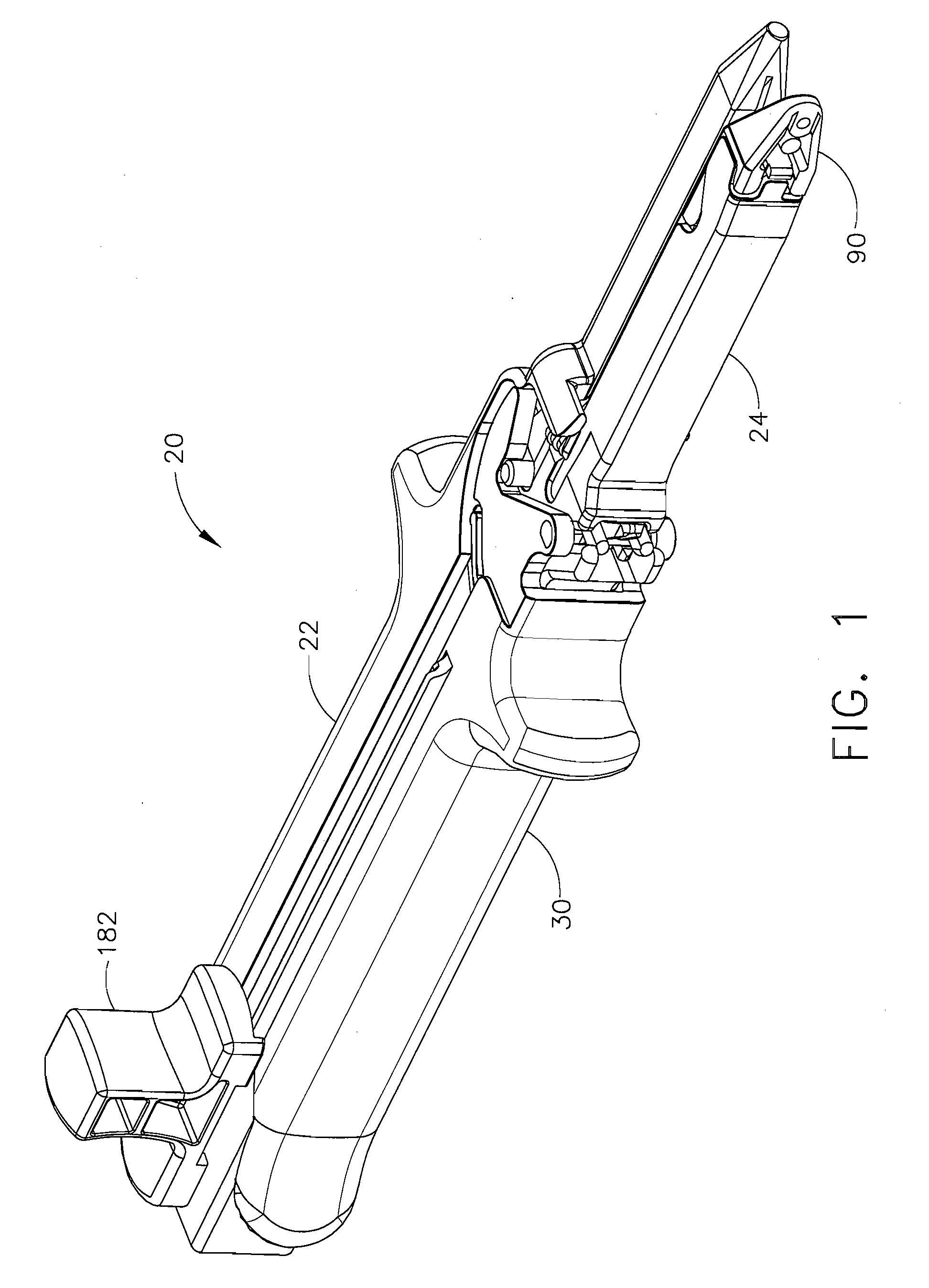
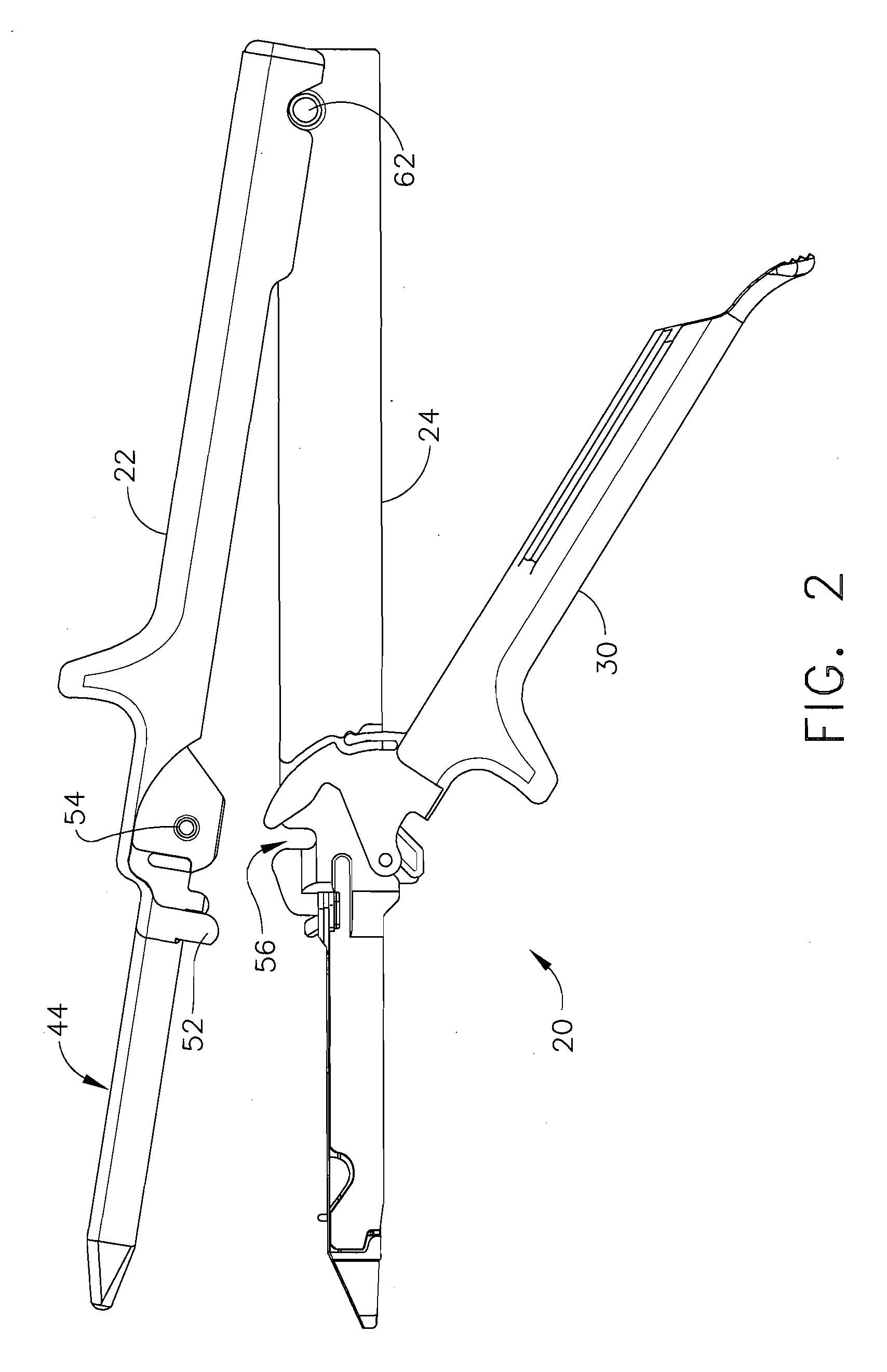
[0036]Referring now to the drawing figures, in which like numerals indicate like elements throughout the views, FIGS. 1 through 3 illustrate a first exemplary surgical stapler 20 of the present invention. The body of stapler 20 includes an upper jaw member 22, a lower jaw member 24, and a latching member 30. Latching member 30 is pivotable relative to the upper and lower jaws members 22, 24, as shown in FIGS. 2-3. Latching member 30 can be pivoted through a series of different latching states to lock the stapler closed for use or to open the stapler varying degrees to allow for adjustment of tissue within the stapler, the replacement of a staple cartridge, or disassembly of the stapler. Upon completion of a surgical procedure, latching member 30 can be pivoted to a fully open position to allow stapler 20 to be disassembled in preparation for the resterilization and reuse of portions of the stapler.

[0037]As shown in FIGS. 4 and 5, upper jaw 22 comprises a single piece, elongated chan...


PUM

PropertyMeasurementUnit
time intensiveaaaaaaaaaa
timeaaaaaaaaaa
lengthaaaaaaaaaa

Abstract

A partially reusable surgical stapler for deploying staples into tissue. The stapler has a body with a distal end, a proximal end and a longitudinal axis therebetween. The proximal end includes a handle while the distal end includes a staple cartridge holder and an opposing anvil. The stapler also has an actuator module for deploying staples. The actuator module includes at least one longitudinally movable member for sequentially ejecting staples towards the anvil. The actuator module is readily removable and replaceable to and from the body. The components of the stapler body can be disassembled, reconditioned and reassembled for reuse in a different surgical procedure.

Description

FIELD OF THE INVENTION[0001]The present invention relates generally to surgical stapling instruments and, more particularly, to a surgical stapler which can be disassembled and portions reconditioned and sterilized for reuse in subsequent surgical procedures, and which includes a removable actuating module that can be reused with multiple staple cartridges during a single patient procedure.BACKGROUND OF THE INVENTION[0002]Before surgical staplers were introduced, surgeons had to spend a great deal of time sewing the tissue of patients back together. This was the most time intensive aspect of a surgical procedure. Surgical staplers have decreased the amount of time that a user spends sewing tissue back together. Such surgical staplers are described in the following issued U.S. patents which are hereby incorporated herein by reference: U.S. Pat. No. 4,633,861 Chow et al.; U.S. Pat. No. 4,633,874 Chow et al.; and U.S. Pat. No. 5,129,570 Schulze et al.[0003]One concern with surgical sta...

Claims


Application Information

Patent Timeline
Patent Type & Authority Applications(United States)
IPC IPC(8): A61B17/068
CPCA61B17/07207A61B2017/07285A61B2017/0725A61B2017/0023
Inventor NALAGATLA, ANIL K.PATEL, SUDHIR B.PRADHAN, DEBASISH
Owner CILAG GMBH INT
Why Eureka
Try Eureka