Adjustable Rear Iron Sight for a Fire Arm

a rear iron sight and fire arm technology, applied in the direction of sighting devices, weapon components, weapons, etc., can solve the problems of inconvenient use, loss of initial zero range setting, and increments of elevation too large to achieve the effect of preventing looseness

Inactive Publication Date: 2012-03-15
NEUFELD HOWARD
View PDF10 Cites 2 Cited by
  • Summary
  • Abstract
  • Description
  • Claims
  • Application Information

AI Technical Summary

Benefits of technology

[0017]Preferably the wheel is readily removable and replaceable for replacement with a second wheel having a cam with a different profile of the cam surface where the cam spiral cam surface of each wheel has a profile of radius changes calibrated relative to a different shot load.
[0059]To provide allowance to adjust elevation for the zero range, a vertical elevation screw is contained in the aperture mounting block. The point of the vertical elevation screw rests on the profiled section of the interchangeable multi position cam. With the cam set to its lowest setting, adjusting elevation for the zero range can be performed. Turning the screw clockwise causes the aperture mounting block to raise (containing the aperture block and aperture) as a result moving the point of impact higher. Turning the screw counter-clockwise causes the aperture mounting block to lower (containing the aperture block and aperture) as a result moving the point of impact lower.
[0062]Quick adjustments to the desired distance setting are ensured by fact that the sight is always ready to be adjusted. The precision fit of the parts controlling the linear vertical movement prevent any looseness that require additional parts to control in some designs of the prior art. Adjustment to any setting is always less than 1 turn.

Problems solved by technology

However the fine threads of the vertical adjustment screw often required multiple complete and partial turns to get to the correct setting, with the likelihood of making a mistake in counting that would result in an incorrect setting and also losing the initial zero range setting.
Even when the sights have markings these are often difficult to read and generic, that is they require knowledge of the trajectory of the firearm / load combination in order to adjust the single elevation screw to the correct setting.
The increments of elevation are also too large to be useful for hunting.

Method used


Image

  • Adjustable Rear Iron Sight for a Fire Arm
  • Adjustable Rear Iron Sight for a Fire Arm
  • Adjustable Rear Iron Sight for a Fire Arm

Examples


Embodiment Construction

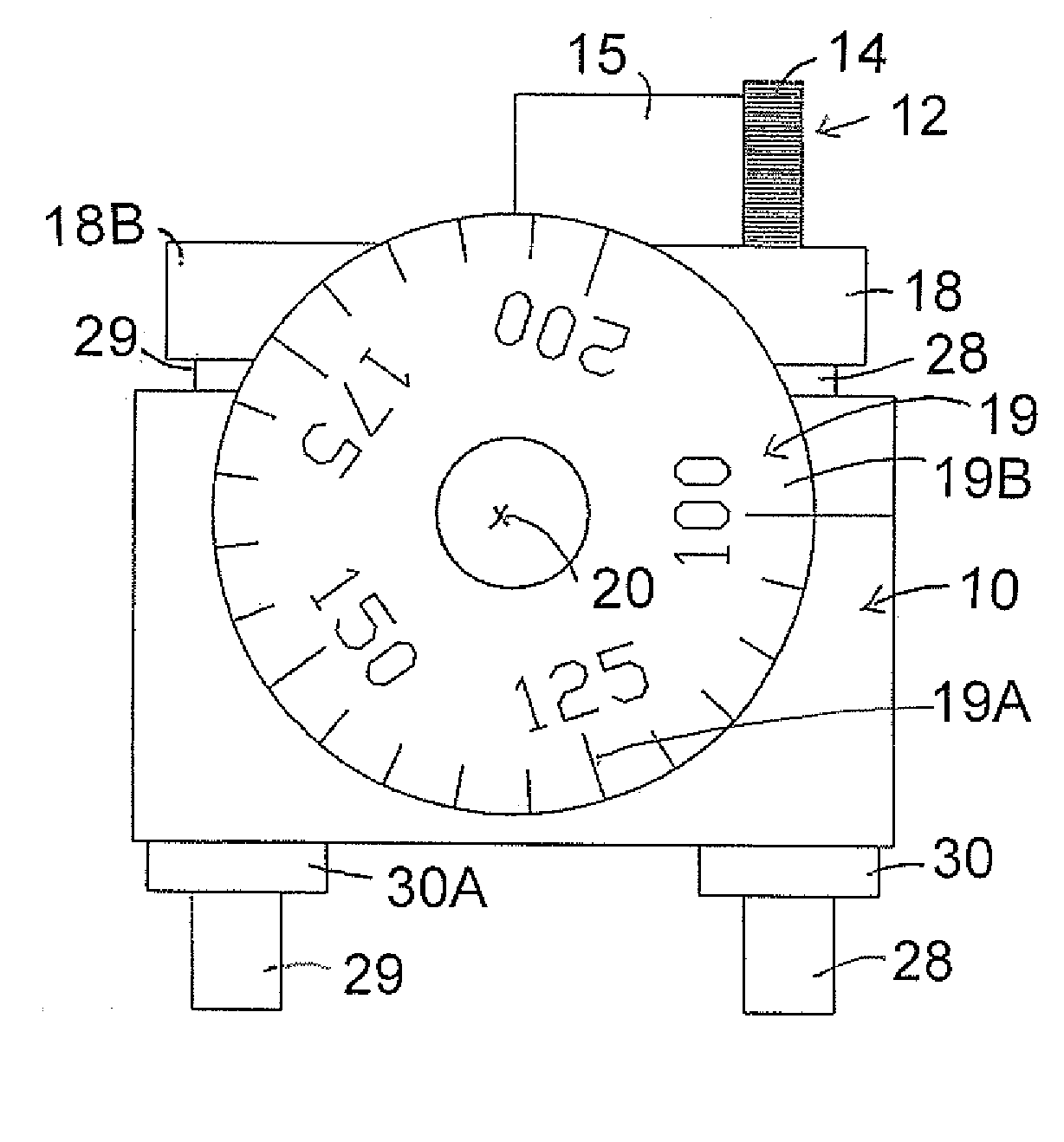
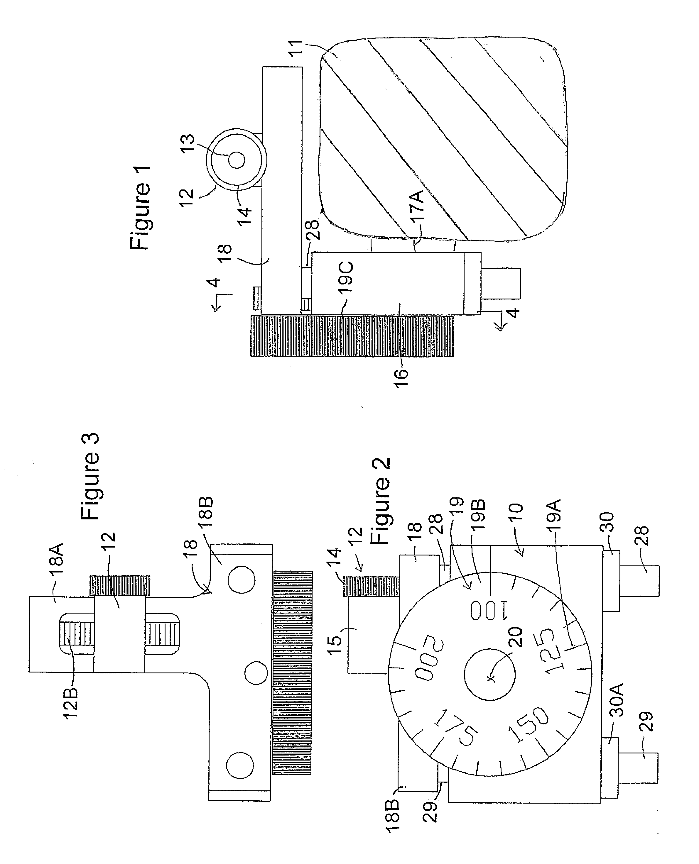
[0072]An adjustable rear iron sight 10 is provided for a firearm 11 for cooperation with a fixed front sight (not shown) where the user aligns the front and rear sights to aim the fire arm in a required direction.

[0073]The sight comprises a rear sighting element 12 which is shown in the form of an aperture 13 carried in a screw-in insert portion 14 for mounting in a housing 15. This is mounted generally at a rear of the fire arm and defines a visible alignment portion defined by the aperture for visual alignment by the user with the front sighting element (not shown). Other types of sighting elements can be used which allow the user to locate the rear sight relative to the front sight as are well known in the industry.

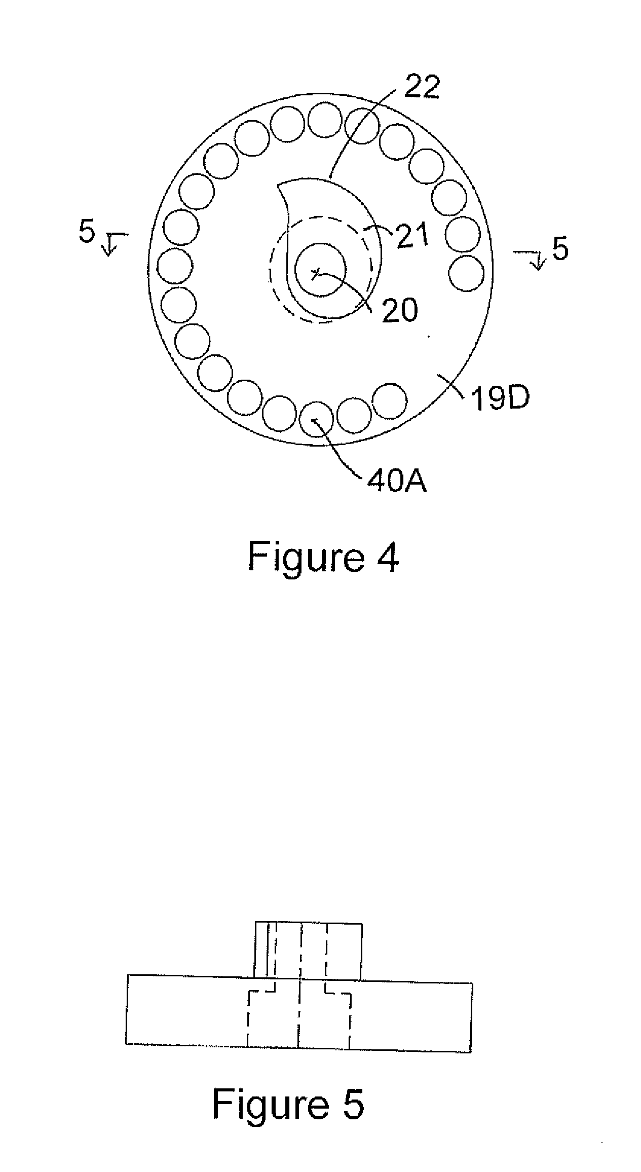
[0074]In general, the element 12 is carried on an a mounting member in the form of a mounting block 16 having mounting elements 17 for attachment of the mounting member 16 to the firearm 11. An adjustable member 18 is carried on the mounting member 16 and is adjustably...


PUM


Abstract

An adjustable iron sight for firearms includes compensation for projectile drop. The projectile drop compensation moves the sight aperture to compensate for projectile drop. Use of the compensation will allow aiming directly at the target without having to visually compensate for projectile drop. The projectile drop compensation mechanism includes a multi-position manually operable wheel and cam that is profiled to match the trajectory of the particular firearm and load. As there are many possible loads that could be used with a particular firearm, the multi-position cam is interchangeable to allow changing to a cam that is matched to the specific load that is desired.

Description

[0001]In general, the present invention relates to firearms and particularly, the present invention relates to an adjustable rear iron sight for firearms including height adjustment compensation for projectile drop.BACKGROUND OF THE INVENTION[0002]Virtually all firearms are equipped with some type of sighting system to facilitate aiming the weapon. Examples of these sighting systems include telescopic sights, holographic sights, laser sights and iron sights. Iron sights also called open sights, consist of a front sight and a rear sight that the shooter aligns together onto the target he / she is aiming at. Iron sights can be either fixed or adjustable and made from iron or any other material[0003]Adjustable iron sights allow for vertical adjustment called elevation and horizontal adjustment called windage. In use the sight is adjusted so that projectiles fired from the firearm will hit the target at the same point that is seen by aligning the sights to the target. This distance from t...

Claims


Application Information

Patent Timeline
Patent Type & Authority Applications(United States)
IPC IPC(8): F41G1/28
CPCF41G1/28
Inventor NEUFELD, HOWARD
Owner NEUFELD HOWARD
Why Eureka
Try Eureka