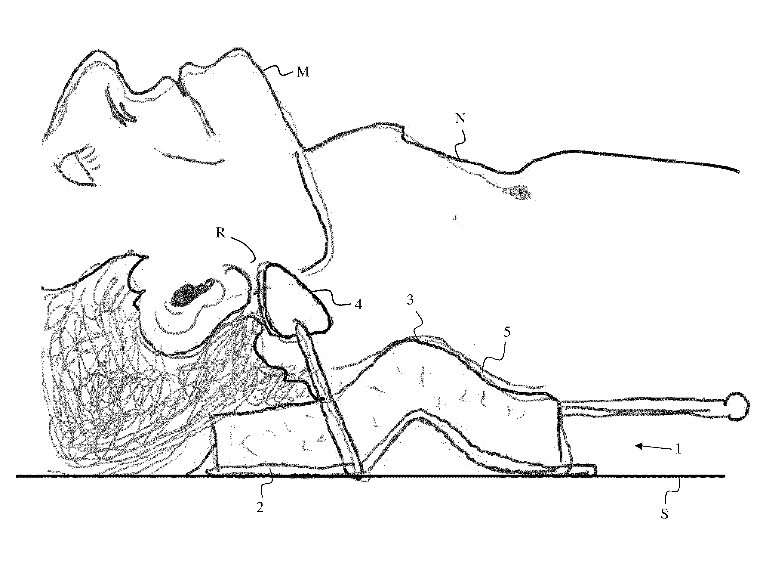
Jaw thrust device and method
a thrust device and thrust device technology, applied in the field of patient airway maintenance, can solve the problems of limiting the ability of medical practitioners to perform procedures on the patient's head and neck, blocking the airway of the patient, and not addressing other parts of the patient's airway
- Summary
- Abstract
- Description
- Claims
- Application Information
AI Technical Summary
Problems solved by technology
Method used
Image
Examples
second embodiment
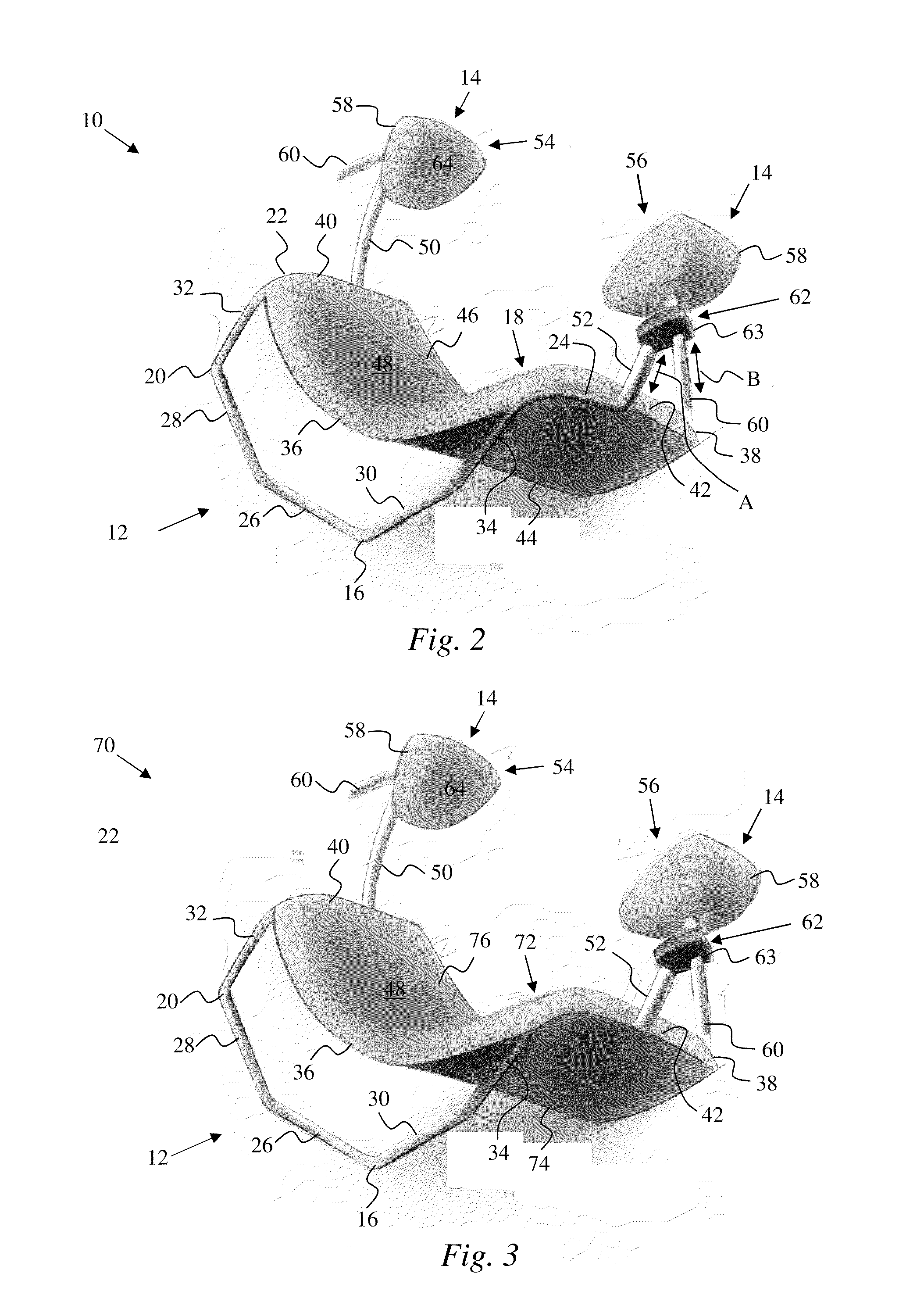
[0067]FIG. 3 illustrates the device 1 schematically represent in FIG. 1. In this embodiment, a device 70 can be substantially identical to the device 10 of FIG. 2, except as noted below. Accordingly, substantially identical features of the device 70 are denoted by the same references numerals as used for the device 10 of a FIG. 2.
[0068]The device 70 can include a neck pad 72 that can be configured to internally receive the pad supports (not visible—see pad supports 22, 24 of FIG. 2, for example) of the frame 16 and a portion of the mounting arms 50, 52. In particular, the pad supports can extend within the neck pad 72 between the backing 74 and the cushion 76 of the neck pad 72. Thus, the neck pad 72 can be connected to the frame 16.
third embodiment
[0069]FIG. 4 illustrates the device 1 schematically represent in FIG. 1. In this embodiment, a device 80 can be substantially identical to the device 10 of FIG. 2, with any exceptions and / or modifications noted below. Accordingly, substantially identical features of the device 80 are denoted by the same references numerals as used for the device 10 of a FIG. 2.
[0070]The device 80 can include a base 82. The base 82 can include a frame 84 and a neck pad 86. The neck pad 86 can include a backing 88 and a cushion 90. The backing 88 and the cushion 90 can include substantially all the features of the backing 44 and the cushion 46 described with reference to the device 10 of FIG. 2. In this exemplary embodiment, the backing 88 of the neck pad 86 can be integrally formed with the frame 84 to define a single, homogenous component. The cushion 90 of the neck pad 86 can be affixed to the backing 88 in any manner described above with reference to FIG. 2.
[0071]The frame 82 can include a polygon...
fourth embodiment
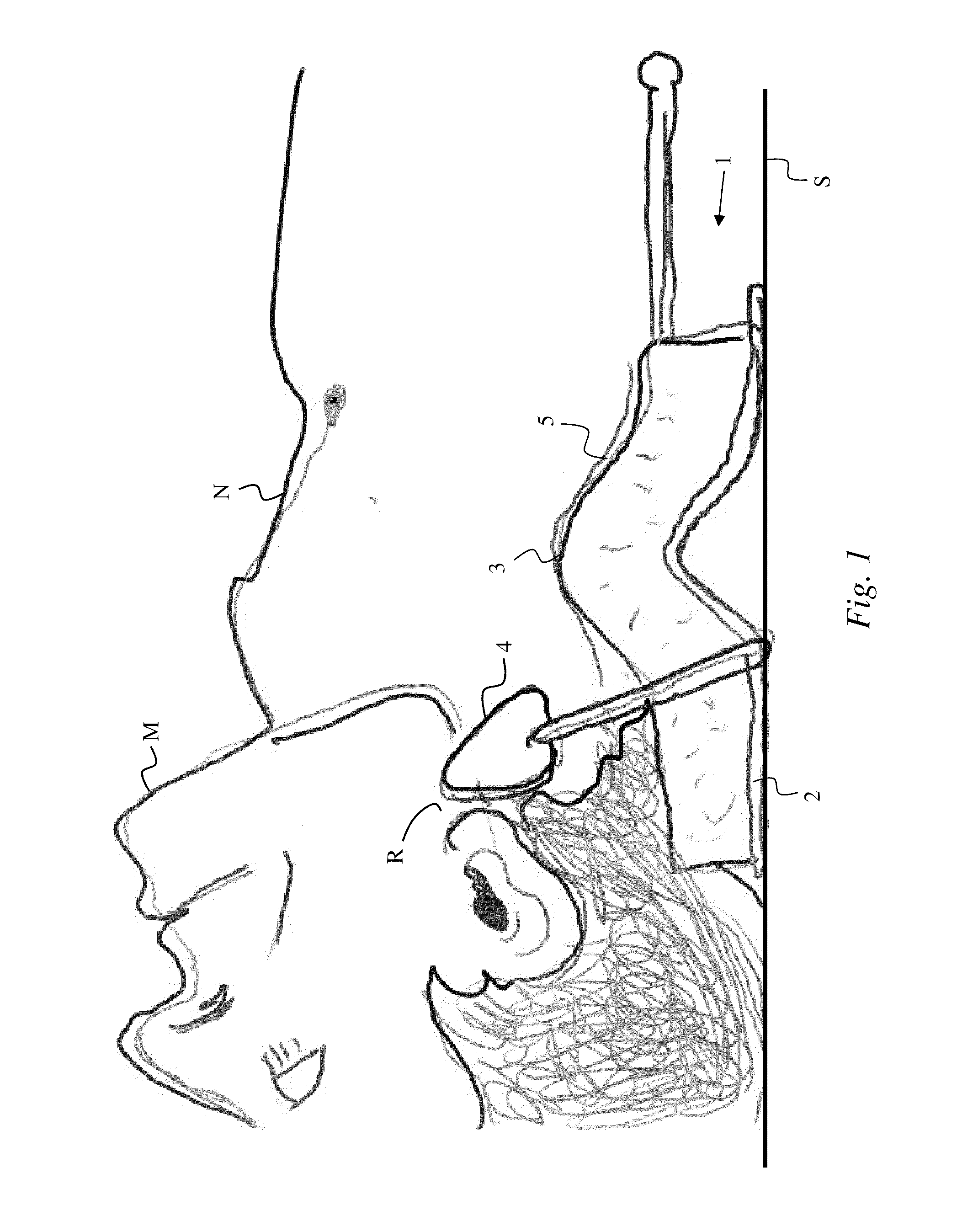
[0086]FIGS. 5-9 illustrate the device 1 schematically represent in FIG. 1. In this embodiment, a device 120 can be substantially identical to the device 10 of FIG. 2, with any exceptions and / or modifications noted below. Description of the device 120 is provided with specific reference to FIGS. 5 and 6.
[0087]The device 120 can include a base 122 and a jaw support 124 that can engage and support a patient's neck and mandible, respectively, as described above with reference to the device 10 of FIG. 2.
[0088]The base 122 can include a frame 126 and a neck pad 128. The jaw support 124 can be connected to the frame 126, as will be described in detail below. The neck pad 128 can be merely placed onto the frame 126 or the neck pad 128 can be positively connected to the frame 126. If the neck pad 128 is positively connected to the frame 126, then the neck pad 128 can either be removably connected or permanently connected to the frame 126. Details of the engagement of the frame 126 by the nec...
PUM
 Abstract
Description
Claims
Application Information
 - R&D
- Intellectual Property
- Life Sciences
- Materials
- Tech Scout
- Unparalleled Data Quality
- Higher Quality Content
- 60% Fewer Hallucinations
Browse by: Latest US Patents, China's latest patents, Technical Efficacy Thesaurus, Application Domain, Technology Topic, Popular Technical Reports.
© 2025 PatSnap. All rights reserved.Legal|Privacy policy|Modern Slavery Act Transparency Statement|Sitemap|About US| Contact US: help@patsnap.com


