Eureka AIR delivers breakthrough ideas for toughest innovation challenges, trusted by R&D personnel around the world.

Spar for sailwings

a sailwing and sail technology, applied in the field of sailwings, can solve the problems of large large amount of spanwise tension needed in the sail, and large upload at the back of the sail, so as to reduce the effect of induced drag

Active Publication Date: 2010-01-07
AURORA FLIGHT SCI CORP
View PDF23 Cites 1 Cited by
  • Summary
  • Abstract
  • Description
  • Claims
  • Application Information

AI Technical Summary

Benefits of technology

[0007]It is therefore a general aspect of the invention to provide a wing structure that will obviate or minimize problems of the type previously described.
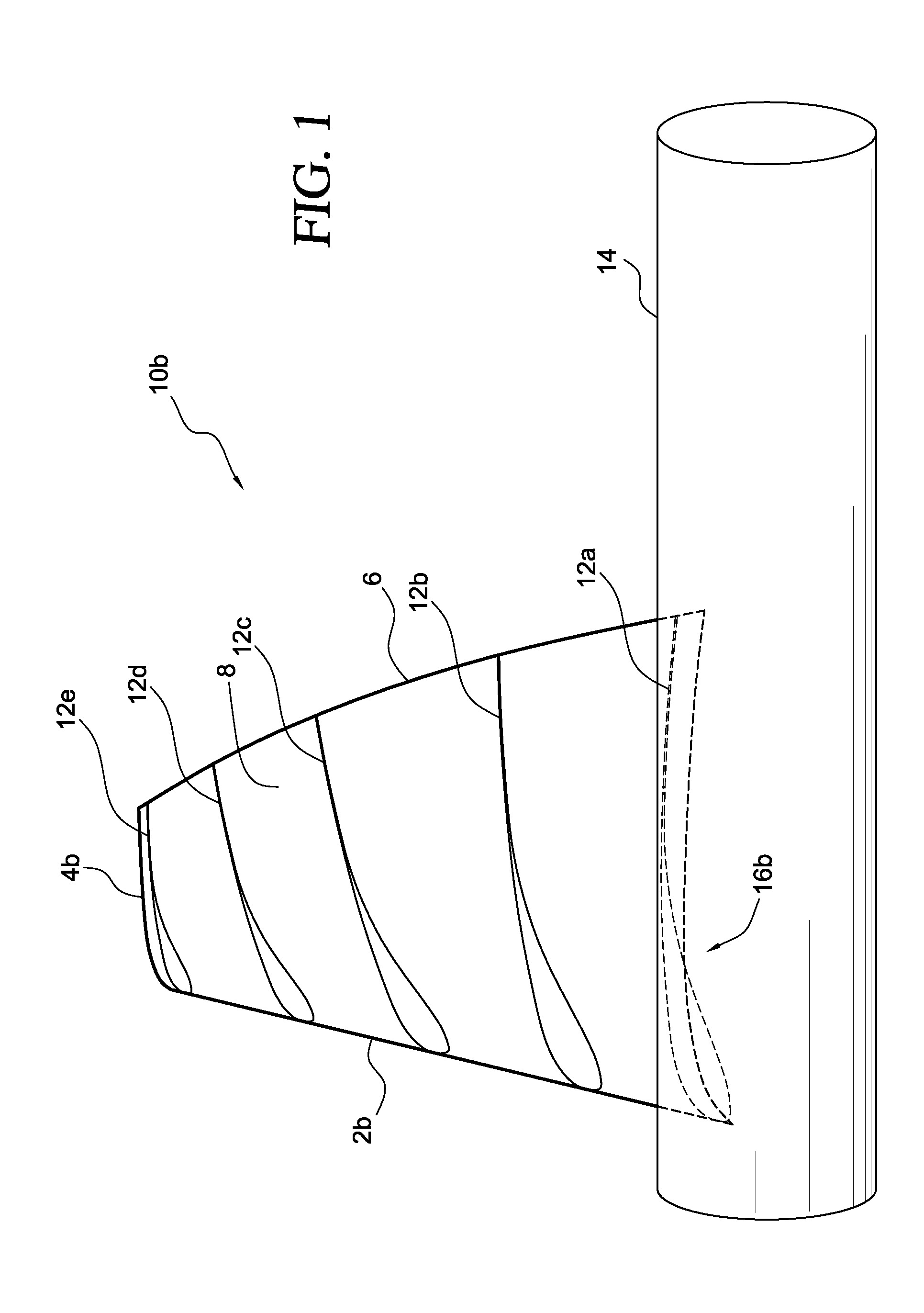
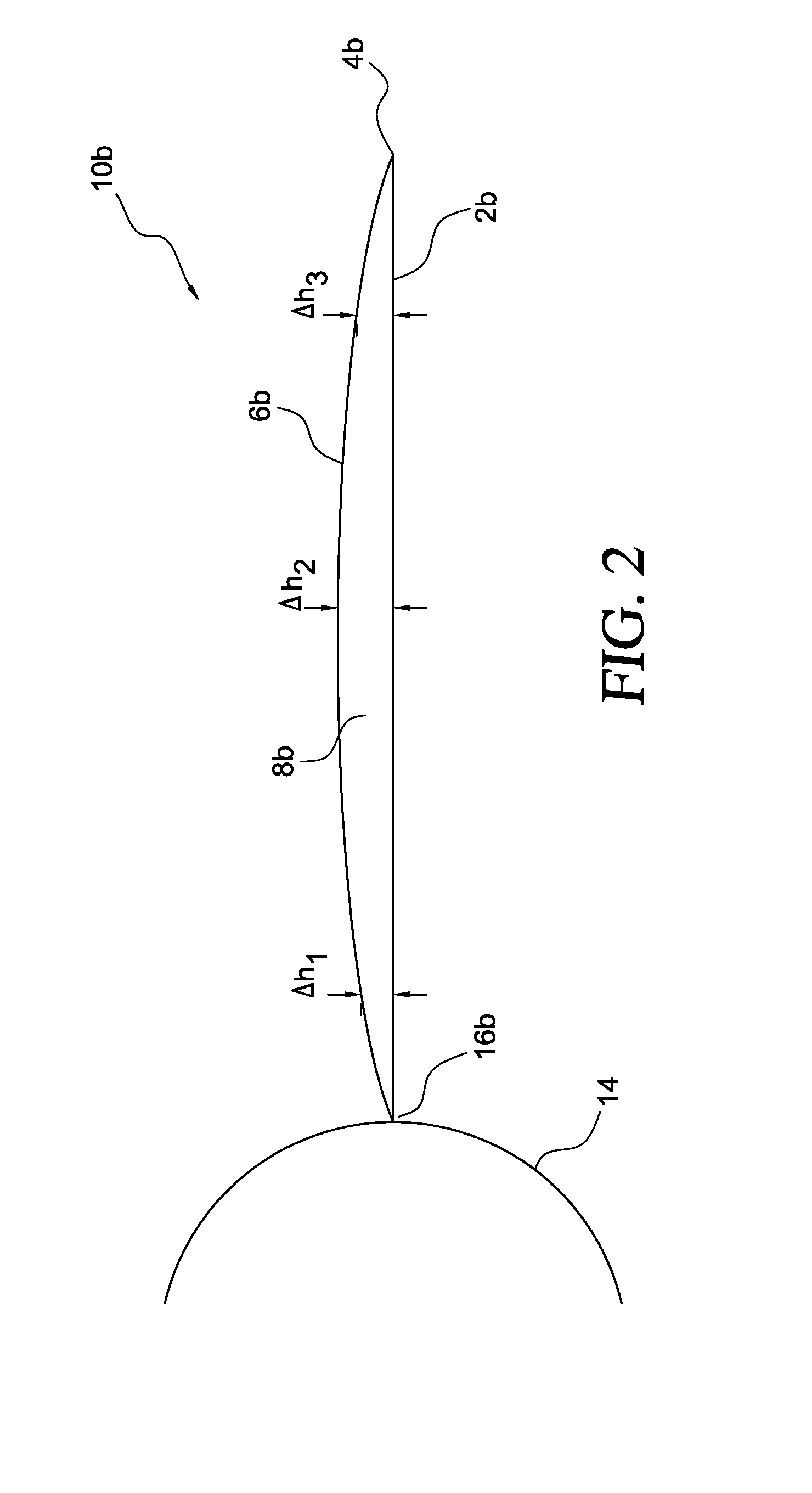
[0010]According to the first aspect, the bend of the front spar is configured to substantially minimize induced drag that results from twisting of the sail wing membrane. According to the first aspect, the curve comprises a substantially catenary curve, the curve comprises a substantially parabolic curve, the curve comprises a substantially hyperbolic curve, and the curve comprises a substantially circular curve.
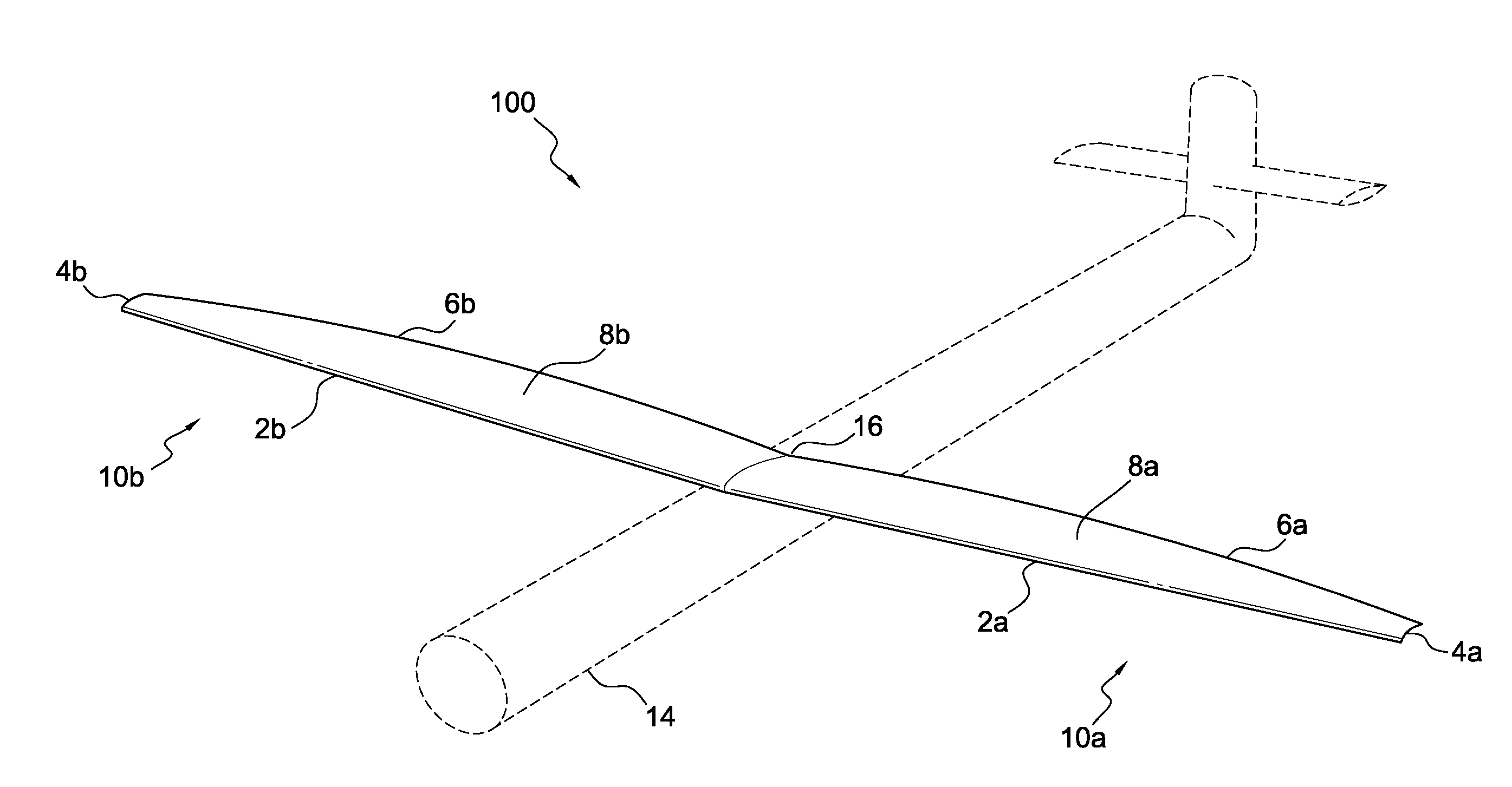
[0013]According to a second aspect of the present invention, a lightweight aircraft is provided comprising: a fuselage; vertical control surfaces appended to the fuselage; horizontal control surfaces appended to the fuselage; and a wing structure appended to the fuselage, wherein the wing structure includes a front spar; a wing structure membrane attached to the front spar; and a tensioned rear wire attached to a trailing edge of the wing structure membrane, such that when the front spar is bent to match a curve of the tensioned trailing edge of the wing structure membrane, the wing structure membrane has substantially little or no twist.
[0015]According to the second aspect, the bend of the front spar is configured to substantially minimize induced drag that results from twisting of the wing structure membrane.
[0020]According to the third aspect, the bend of the front spar is configured to substantially minimize induced drag that results from twisting of the tensioned sail wing membrane.

Problems solved by technology

Previous attempts at using sailboat type membrane sails for aircraft wings have had major problems with controlling the twist of the wing.
A large amount of spanwise tension is needed in the sail, particularly at the trailing edge to control the twist of the airfoil under load.
The wing spar (mast) is well ahead of the centroid of the aerodynamic forces, and this results in a significant upload at the back of the sail.
The higher the tension, the flatter this curve, but this gives a large aft bending moment in the spar.
With tolerable spar loads, the wing might have over 10 degrees twist, which can give poor induced drag, as compared to a more normal wing.

Method used


Image

  • Spar for sailwings
  • Spar for sailwings
  • Spar for sailwings

Examples


Embodiment Construction

[0029]The various features of the preferred embodiments will now be described with reference to the drawing figures, in which like parts are identified with the same reference characters. The following description of the presently contemplated best mode of practicing the invention is not to be taken in a limiting sense, but is provided merely for the purpose of describing the general principles of the invention.

[0030]Light weight aircraft 100, according to an exemplary embodiment, generally comprise aircraft that weigh less than or about 5,000 pounds. According to a further exemplary embodiment, most sail planes can generally be considered to be light weight aircraft, and comprise a wing structure made up of a front spar, a trailing edge cable, and sail wing material (typically a relatively thin membrane material). Other components of the light weight aircraft 100 include a fuselage, vertical and horizontal flight control surfaces, and in most instances, a cockpit (with flight contr...


PUM


Abstract

A sail wing for a lightweight aircraft comprising a membrane; a front spar; and a tensioned rear wire attached to a trailing edge of the membrane, such that when the front spar is bent to match a curve of the tensioned trailing edge of the sail wing membrane, the sail wing membrane has substantially little or no twist, and results in substantially little or no induced drag.

Description

PRIORITY[0001]The present application claims priority under 35 U.S.C. § 119(e) to U.S. Provisional Patent Application Ser. No. 60 / 943,772, filed Jun. 13, 2007, the entire contents of which are herein expressly incorporated by reference.BACKGROUND OF THE INVENTION[0002]1. Field of the Invention[0003]The invention is related to light weight aircraft. More particularly, the invention is related to a system and method for eliminating, or substantially reducing, and controlling the twist of sailwings on lightweight aircraft.[0004]2. Background Art[0005]Previous attempts at using sailboat type membrane sails for aircraft wings have had major problems with controlling the twist of the wing. A large amount of spanwise tension is needed in the sail, particularly at the trailing edge to control the twist of the airfoil under load. The wing spar (mast) is well ahead of the centroid of the aerodynamic forces, and this results in a significant upload at the back of the sail. Normally this load i...

Claims


Application Information

Patent Timeline
IPC IPC(8): B64C3/14B64C3/18B64C31/02
CPCB64C31/02B64C3/18
Inventor BOERTLEIN, NEIL THOMAS
Owner AURORA FLIGHT SCI CORP
Why Eureka
Eureka Blog
Learn More