Translatable thrust inverter for jet engine

a jet engine and thrust reverser technology, which is applied in the direction of jet propulsion plants, power plant arrangements/mountings, air transportation, etc., can solve the problems of preventing the access to the engine during maintenance and therefore not allowing such an extra travel in the downstream direction, and achieve the effect of opening the sliding cowl more simply

Inactive Publication Date: 2010-01-07
SAFRAN NACELLES
View PDF8 Cites 50 Cited by
  • Summary
  • Abstract
  • Description
  • Claims
  • Application Information

AI Technical Summary

Benefits of technology

The technical effect of this patent proposal is that it makes it easier to maintain by allowing the engine's sliding cowl to be opened without having to move its position upstream first.

Problems solved by technology

The technical problem addressed in this patent is how to design a thrust reverser for an aircraft that can be easily maintained and accessed for repair without having to fully disassemble the entire nacelle.

Method used


Image

  • Translatable thrust inverter for jet engine
  • Translatable thrust inverter for jet engine
  • Translatable thrust inverter for jet engine

Examples


Embodiment Construction

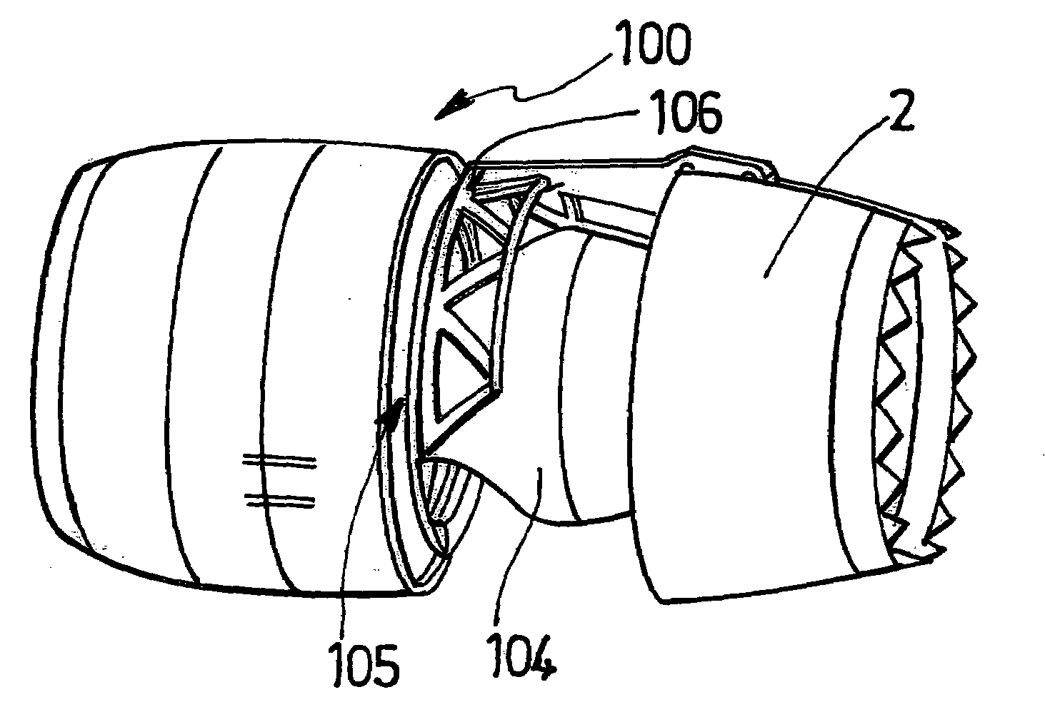
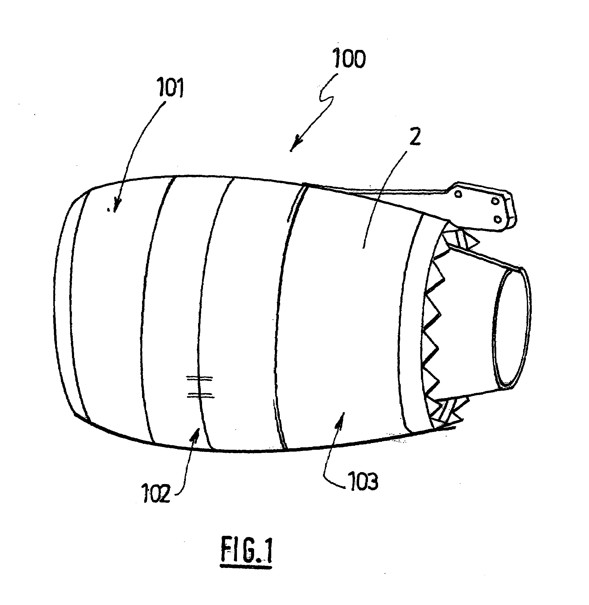
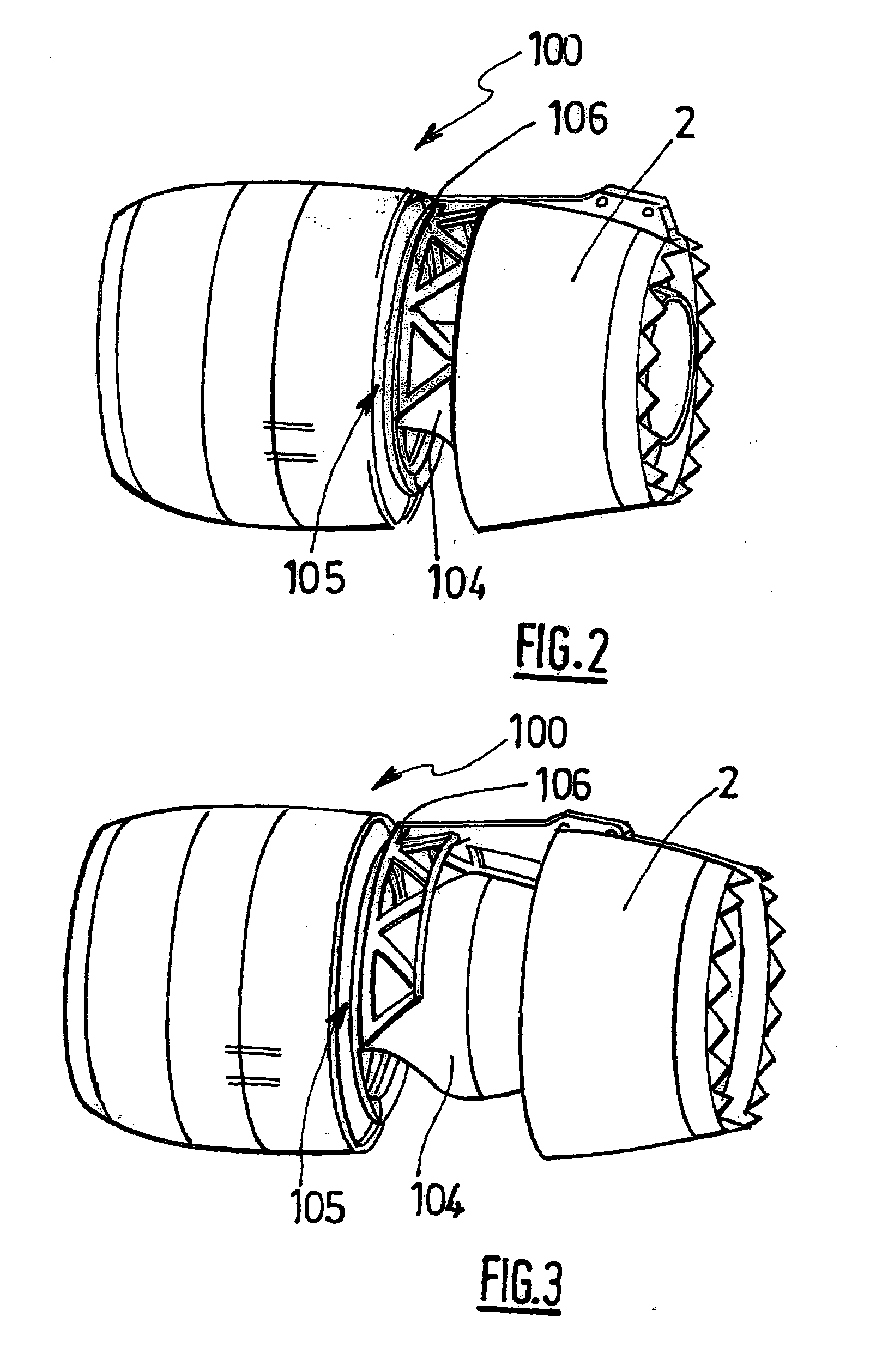
[0034]FIGS. 1 to 3 represent a nacelle 100 for a turbofan.

[0035]The nacelle 100 constitutes a tubular housing for a turbofan (not visible) and serves to channel the airflows which it generates via the blades of a fan (not visible), namely a hot airflow passing through a combustion chamber of the turbofan, and a cold airflow flowing around outside the turbofan.

[0036]The nacelle 100 has a structure comprising a front section 101 forming an air inlet, a midsection 102 surrounding the fan of the turbofan, and a rear section 103 surrounding the turbofan.

[0037]The rear section 103 comprises, on the one hand, an external structure incorporating a thrust reversal system, likewise forming an exhaust nozzle, and, on the other hand, an internal cowling structure 104 of the turbofan which, together with the external structure, defines a duct intended for the circulation of the cold flow.

[0038]The external structure and its thrust reversal system, illustrated in FIGS. 1 to 7, comprise, on the on...


PUM


Abstract

The invention relates to a thrust inverter with grids (5) for a turbojet, that defines at least a portion of the downstream section (103) of a nacelle (100) housing the turbojet, comprising a front frame (105) to be secured to a fixed portion (102) of the nacelle and bearing, on the one side, cylinders (6) for the translational actuation of at least one mobile cowling (2) and, on the other side, grids for inverting the peripheral thrusts, characterised in that the front frame includes a fixed portion for securing the front frame to the fixed portion of the nacelle and bearing the diversion grids, and a portion mounted so as to be capable of translation movement along the longitudinal axis of the nacelle and on which one end of the cowling actuation cylinders is attached, wherein the fixed and mobile portions of the front frame can be removably connected to each other by locking means.

Description


Claims


Application Information

Patent Timeline
Owner SAFRAN NACELLES
Why Eureka
Try Eureka