
Water softener having timer control valve

a water softener and timer technology, applied in the direction of valve operating means/release devices, water/sewage treatment by ion exchange, separation processes, etc., can solve the problems of user confusion, user may not be aware of the remaining time for regeneration, and difficulty in clearly determining the appropriate regeneration process time, etc., to reduce the amount of regeneration agent used, reduce installation costs, and effectively view the progress

Active Publication Date: 2017-01-31
WOONGJIN COWAY
View PDF16 Cites 0 Cited by
  • Summary
  • Abstract
  • Description
  • Claims
  • Application Information

AI Technical Summary

Benefits of technology

The water softener described in this patent has several technical benefits. The first advantage is that the softener only regenerates for the amount of time set by a timer, so less regeneration agent is used. This not only saves money, but also reduces the risk of electrical shorts and simplifies installation. The softener also has a multi-tank design that allows for quick distribution of soft water to the user, and a small size and ease of installation. Additionally, the softener has a unique design that allows for easy opening of the regeneration tank cap without needing a separate drain valve, reducing the risk of injury. The softener also maintains a consistent amount of soft water by supplying a constant amount of regeneration water to the resin tanks.

Problems solved by technology

In addition, due to factors, such as overage pipes or water pollution, tap water may contain various kinds of heavy metals (ions), such as iron, zinc, lead, mercury, etc. that have a negative influence on the human body.
If the sodium ingredients of the ion exchange resins are successfully regenerated, the regeneration process can be terminated; however, it is difficult to clearly determine the appropriate regeneration process time.
However, the water softener having the mechanical timer is problematic in that a user may not clearly know whether the current operation mode is regeneration mode or not.
Further, even when the user knows that the current mode is regeneration mode, the user may not be aware of the remaining time for which regeneration should be executed.
However, the water softener is typically used in moist spaces, so that the electric timer or the electric signal controller may form a short circuit in the water softener and remarkably increase the production expenses of the water softener.
In the related art, raw water under pressure is contained in the regeneration tank, so that the interior of the regeneration tank is pressurized and it is difficult to open the cap because it is under pressure.
Further, when the cap is opened, the cap may suddenly explode off due to the pressure and may injure a user.
However, the drain valve is typically located at a position that a user's hand cannot easily reach, thus being difficult to manipulate.
Further, when a user carelessly opens the regeneration tank cap without opening the drain valve, the user may be injured by the exploding cap.
However, when water at a temperature that was previously set by a user is supplied from a water tap to the water softener having one resin tank, the flow path of ion-exchanged soft water through which the soft water must pass prior to being distributed to the user is too long and an excessive amount of water stagnates in the flow path and does not move, so that an excessive amount of time is required to distribute the soft water at the temperature selected by the user.
Although two or more resin tanks may realize easy control of the water temperature, they undesirably increase the size of the water softener, thus making installation of the water softener unfavorable.
Further, the conventional water softener does not allow a user to be aware of the total amount of distributed soft water, so that the user may not clearly determine the appropriate regeneration timing.
However, the flow sensor may form an electric short circuit.
However, the water softener using the electric timer instead of the mechanical timer is problematic in that an electric short circuit may occur in the water softener because the water softener is typically used in moist environments as described above, and, further, the electric timer excessively increases the production cost of the water softener.

Method used


Image

  • Water softener having timer control valve
  • Water softener having timer control valve
  • Water softener having timer control valve

Examples


Embodiment Construction

[0070]1. Construction of Water Softener

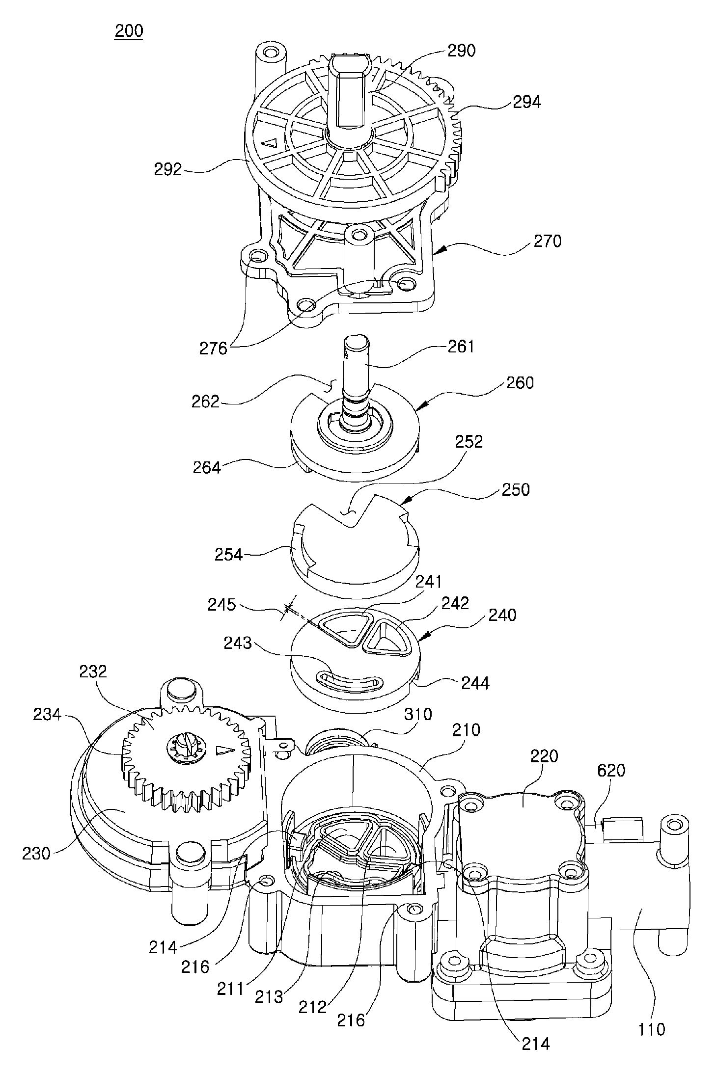
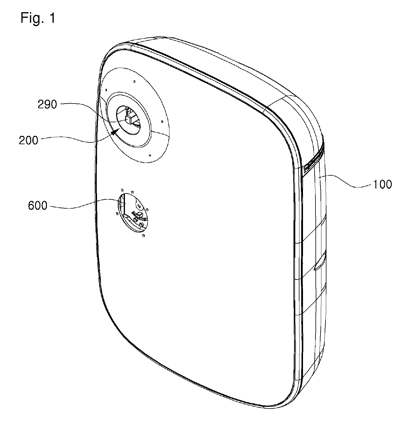
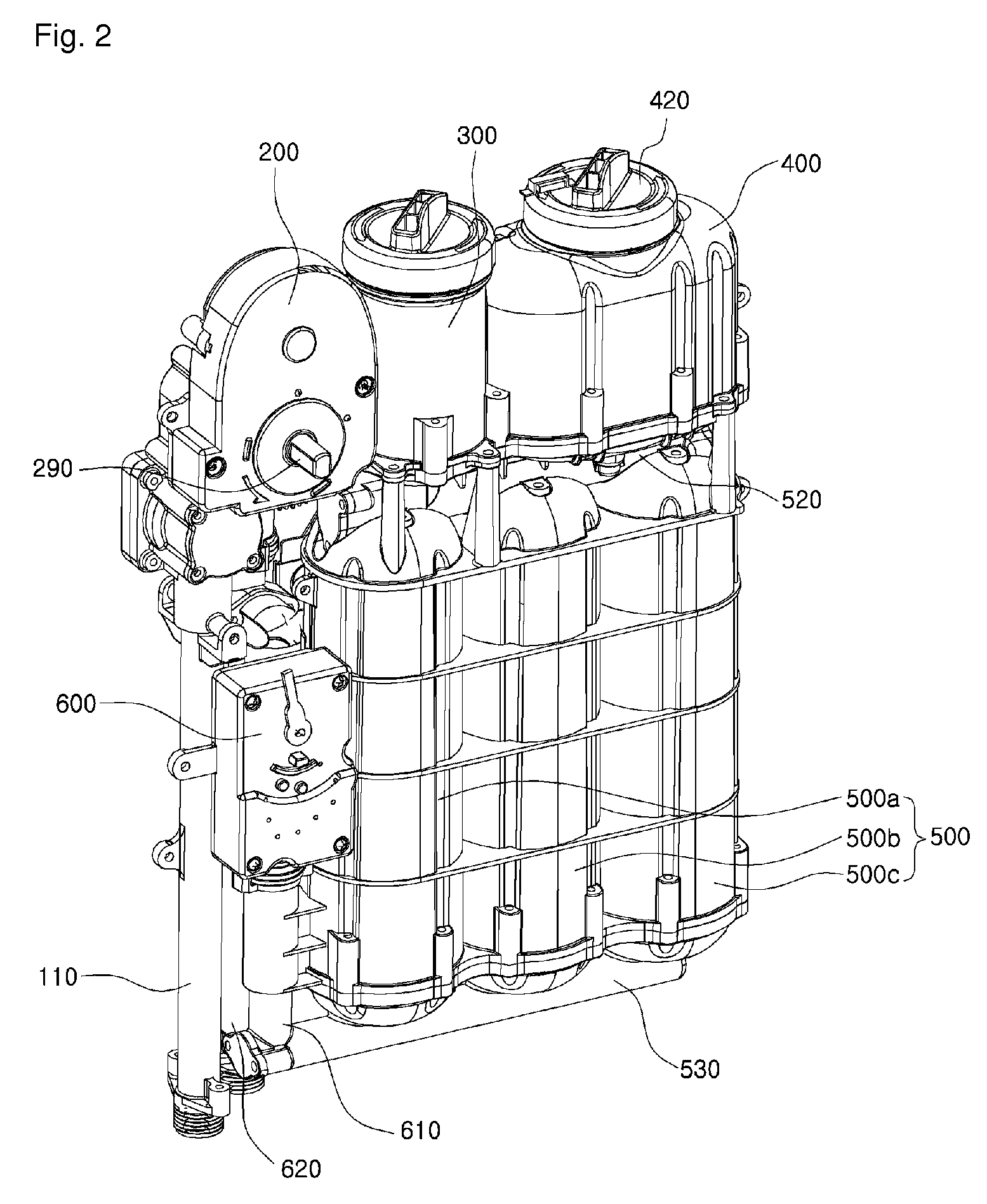
[0071]Hereinbelow, the construction of a water softener according to the present invention will be described with reference to FIG. 1 through FIG. 7. FIG. 1 through FIG. 3 are perspective views of the water softener according to the present invention. FIG. 4 is a sectional view of the water softener according to the present invention. FIG. 5 through FIG. 7 are perspective views of a timer control valve.

[0072]1.1 Schematic Description of Elements

[0073]FIG. 1 is a perspective view illustrating the appearance of the water softener according to the present invention. In FIG. 1, an outer casing 100, which covers and protects the internal elements of the water softener, a valve shaft 290 to which a user-operable valve control unit 295 (see FIG. 9) is attached, and an integrating flowmeter 600, which allows the user to view the amount of distributed soft water, are shown. The cover of the integrating flowmeter 600 is not shown in FIG. 1.

[0074]FIG. 2 t...


PUM

PropertyMeasurementUnit
inner diameteraaaaaaaaaa
volumeaaaaaaaaaa
diameteraaaaaaaaaa

Abstract

A water pressure regenerated type water softener including: a timer control valve having a valve control unit rotated by a timer spring and into which raw water is supplied; a plurality of conduits into which the raw water selectively flows under the control of the timer control valve; a regeneration tank communicating with a regeneration tank inlet conduit of the conduits; and a resin tank unit receiving regeneration water flowing from the regeneration tank and containing an ion exchange resin therein. The water softener can be operated in one of stop mode, soft water mode, raw water mode and regeneration mode under the control of the valve control unit. When regeneration mode is selected, the valve control unit rotates to stop mode by the timer spring after a preset amount of time has elapsed.

Description

TECHNICAL FIELD[0001]The present invention relates, in general, to a water pressure regenerated type water softener having a timer control valve and, more particularly, to a water pressure regenerated type water softener, which includes a timer control valve having a valve control unit rotated by a timer spring and receiving raw water, a plurality of conduits through which inlet raw water selectively flows under the control of the timer control valve, a regeneration tank communicating with a regeneration tank inlet conduit that is one of the plurality of conduits, and a resin tank unit to which regeneration water produced by the regeneration tank may be fed and which stores an ion exchange resin therein, wherein the water softener can execute a stop mode, a soft water mode, a raw water mode or a regeneration mode selected by manipulating the valve control unit and, when regeneration mode is selected, the valve control unit can be rotated for a preset time by the timer spring so as t...

Claims


Application Information

Patent Timeline
Patent Type & Authority Patents(United States)
IPC IPC(8): C02F1/42F16K31/48
CPCC02F1/42F16K31/48C02F2201/005
Inventor YOON, SUNG HUNAN, JOONG KEUNKIM, WON TAEPARK, CHUN HO
Owner WOONGJIN COWAY
Learn More