Beverage Label System and Dispenser

Inactive Publication Date: 2010-01-14
NEWMARK CHARLES M
View PDF26 Cites 12 Cited by
  • Summary
  • Abstract
  • Description
  • Claims
  • Application Information

AI Technical Summary

Problems solved by technology

However, this prior art fails to teach a means to rapidly supply such labels at the time the bottled beverages are removed from a refrigerator or other storage means and distributed to individuals.
Further, the prior art methods do not provide a convenient

Method used


Image

  • Beverage Label System and Dispenser
  • Beverage Label System and Dispenser
  • Beverage Label System and Dispenser

Examples


Embodiment Construction

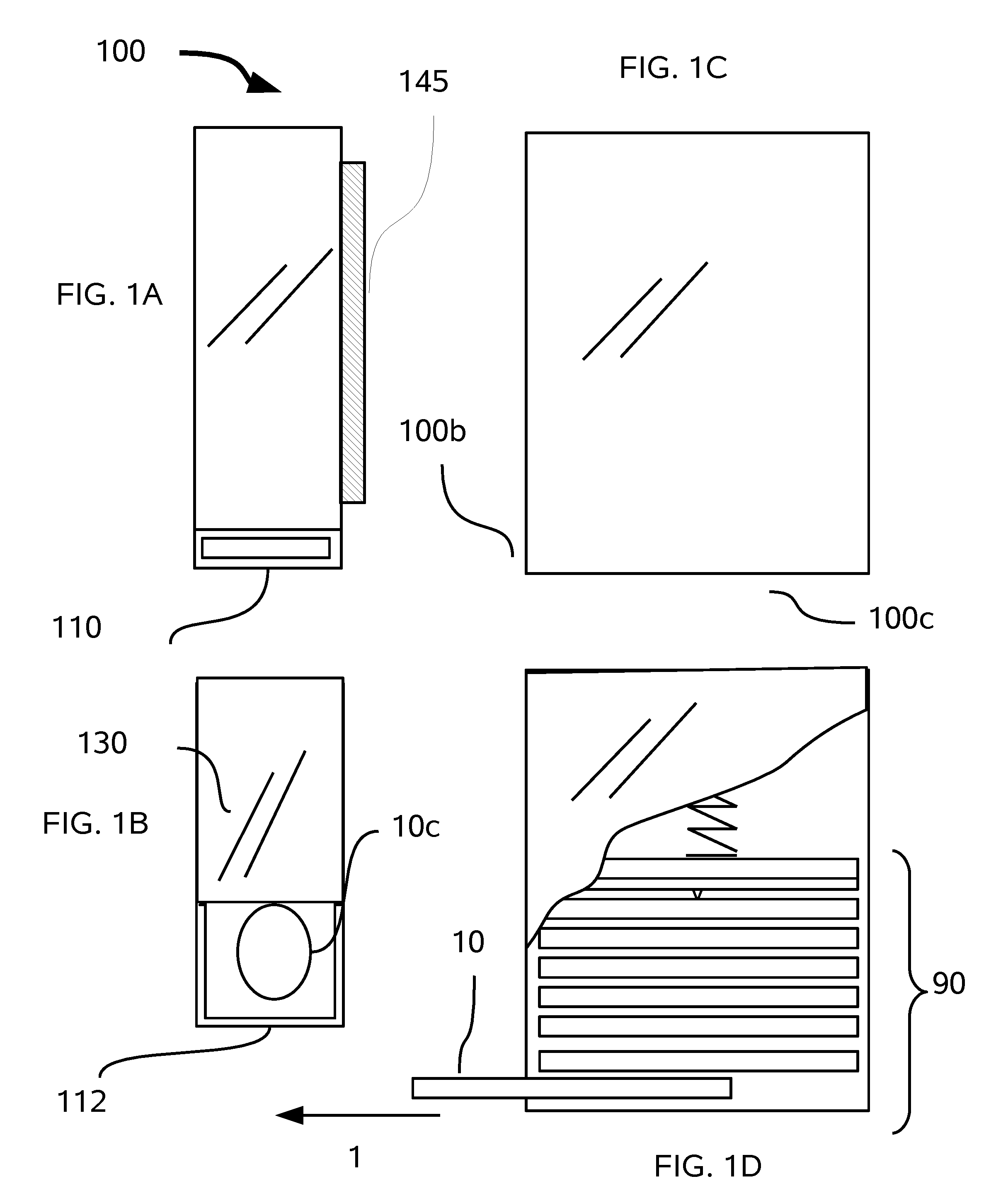
[0019]Referring to FIGS. 1 through 6, wherein like reference numerals refer to like components in the various views, there is illustrated therein a new and improved beverage label system and dispenser, generally denominated 100 herein.

[0020]In accordance with the present invention FIG. 1A-C illustrate a first embodiment in which dispenser 100 contains a plurality of labels 10, preferably arranged in a stack 90. Dispenser 100 is generally in the shape of box having six sides and a slit opening 110 at the bottom edge 100b.

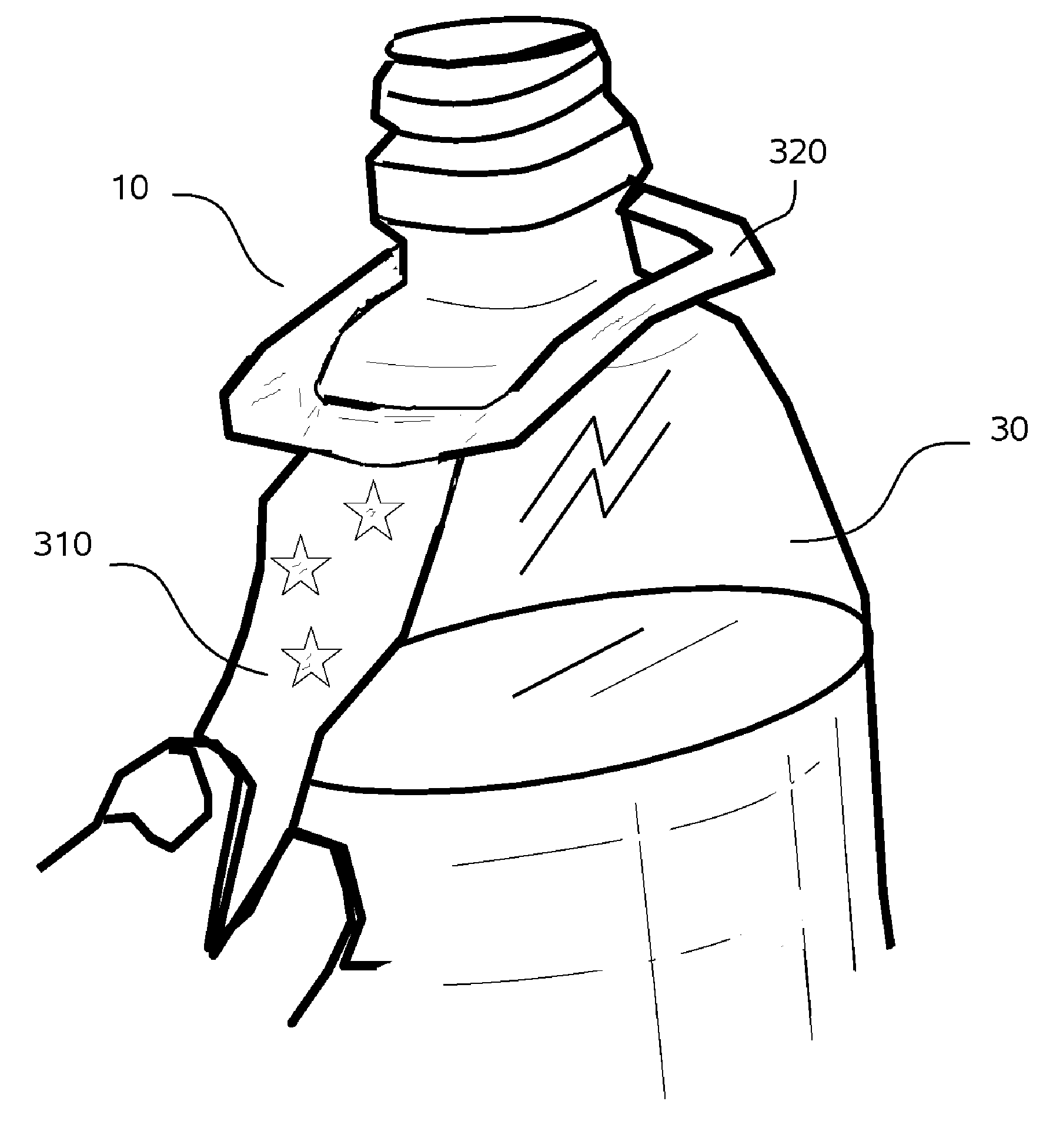
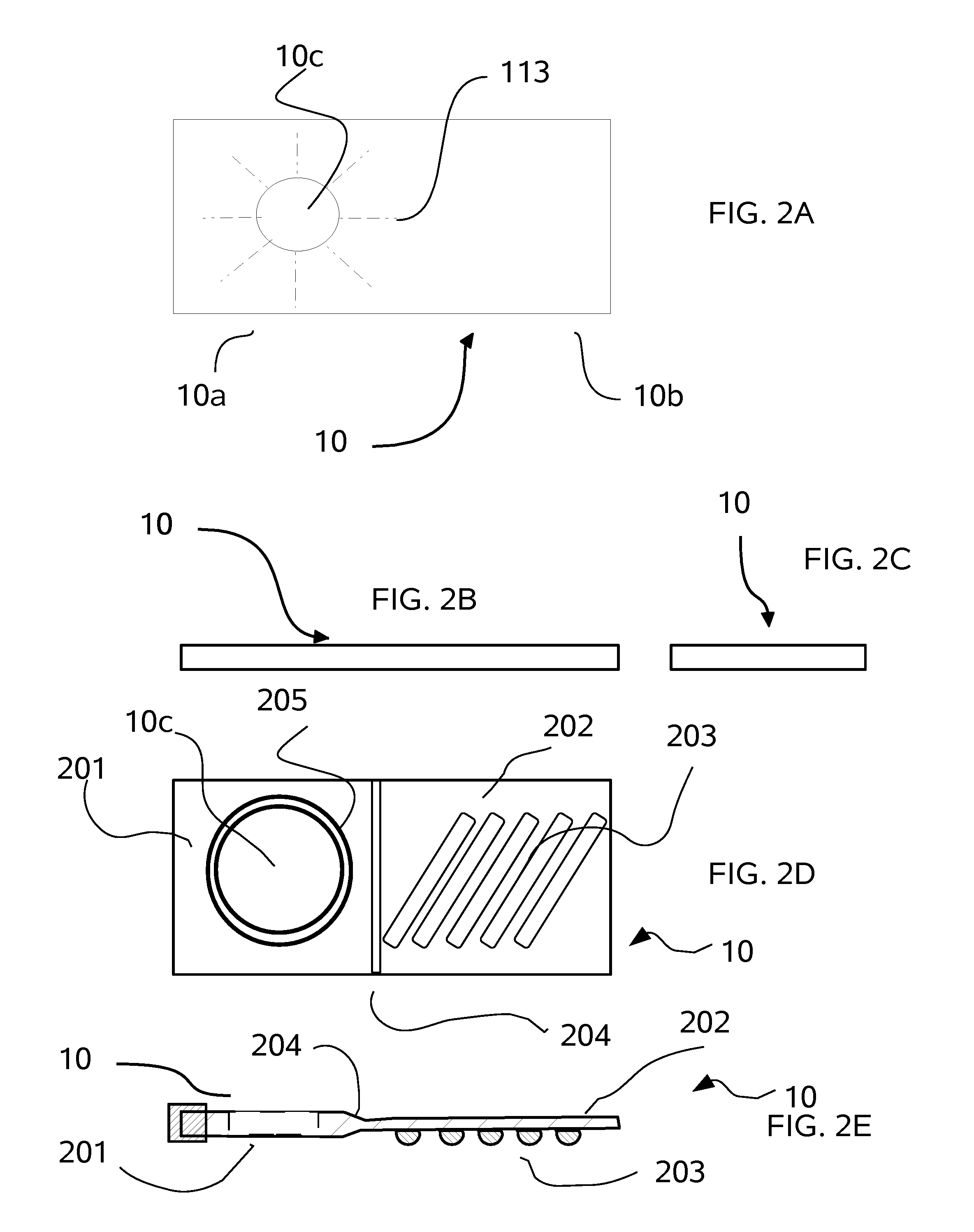
[0021]A stack 90 of substantially planar labels 10 is disposed in the box shaped dispenser 100, each label 10 having an opening on side 10a and a label portion 10b on the other. The labels 10 are arranged in stack 90 with each open side 10a facing the slit 110. It should be noted that each label 10 is thinner than height of the slit 110. The open side 10a is intended to be inserted around the neck of a bottle to be personally labeled whereas the opposite side 10b is...


PUM


Abstract

A bottle label means having a hole on one side and an ID means on the other is optionally dispensed from a roll or stack by inserting the neck of the bottle into the hole whereby the removal provide another label that is ready for removal by a second bottle. Preferably, the labels are not identical so that each bottle has a unique identification on it without the need to write on the label.

Description

CROSS REFERENCE TO RELATED APPLICATIONS [0001]The present application claims priority to the U.S. Provisional patent application of the same title filed on Jul. 9, 2008, having application Ser. No. 61 / 079,427, which is incorporated herein by reference.BACKGROUND OF INVENTION [0002]The present invention relates to labels for personally marking beverage and similarly shaped bottles and a method for dispensing and applying such labels.[0003]Prior methods of marking beverage bottles most similar to the present invention are disclosed in the following US patents and applications, which are incorporated herein by reference: U.S. Pat. No. 1,350,890 (Tanzey, Aug. 24, 1920); U.S. Pat. No. 1,971,528 (Klebanow, Aug. 28, 1934); U.S. Pat. No. D370,386 (Pallesen, Jun. 4, 1996); U.S. Pat. No. D412,938 (Kesselring et al., Aug. 17, 1999); and 2005 / 0138854 A1 (Simmons, Jun. 30, 2005).[0004]However, this prior art fails to teach a means to rapidly supply such labels at the time the bottled beverages a...

Claims


Application Information

Patent Timeline
IPC IPC(8): G07F11/68G09F3/00
CPCB65C3/18B65C7/00G09F3/10B65C11/00G09F3/02B65C9/262
Inventor NEWMARK, CHARLES M.
Owner NEWMARK CHARLES M
Why Eureka
Try Eureka