
Method and apparatus for printing images

a technology of printing apparatus and image, applied in the field of image printing system, can solve the problems of inconvenient use, inconvenient use, density loss, etc., and achieve the effect of accurate and clear application of images

Inactive Publication Date: 2010-01-21
SAIN TODD
View PDF24 Cites 16 Cited by
  • Summary
  • Abstract
  • Description
  • Claims
  • Application Information

AI Technical Summary

Benefits of technology

"The invention is an image printing system that controls in-flight ink droplets to create clear and accurate images on various substrates. The system can print on flat, curved, spherical, and irregular surfaces. It also allows for control of droplet direction and velocity during image creation. The system includes an electronic image storage, a print head, and a voltage generator to generate an electrical charge with the opposite polarity of the ink. This charge is applied proximate the object to accelerate the ink being applied from the print head onto the object. The object may also have a charge conductive layer for receiving the induced electrical charge. The system can hold multiple objects in a fixed orientation while printing and includes an object holder for positioning the object correctly for printing. The method involves providing a print head, applying the ink with a predetermined charge polarity, and generating an opposite charge to accelerate the ink being applied onto the object."

Problems solved by technology

However, these methods do not address the issue of varying distances between the substrates to be printed and print head; rather, they attempt to maintain a constant distance by curving the travel of the print head relative to the curvature of the substrate, or by moving the substrate during ink projection to maintain this distance.
Additionally, these methods do not compensate for droplet loss due to droplets that are directed away from the substrate, causing density loss and an image that is out-of-focus or slightly fuzzy.

Method used


Image

  • Method and apparatus for printing images
  • Method and apparatus for printing images
  • Method and apparatus for printing images

Examples


Embodiment Construction

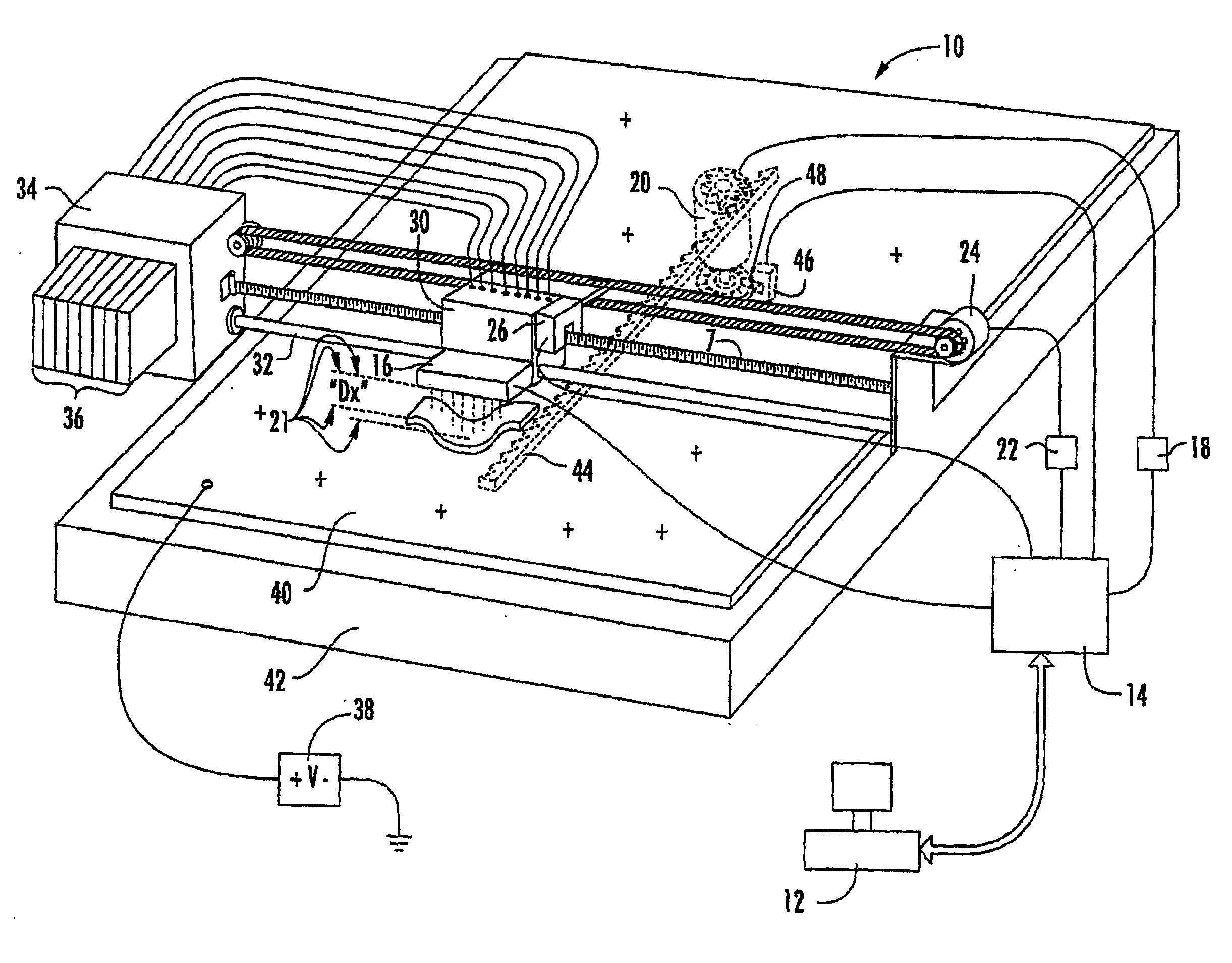
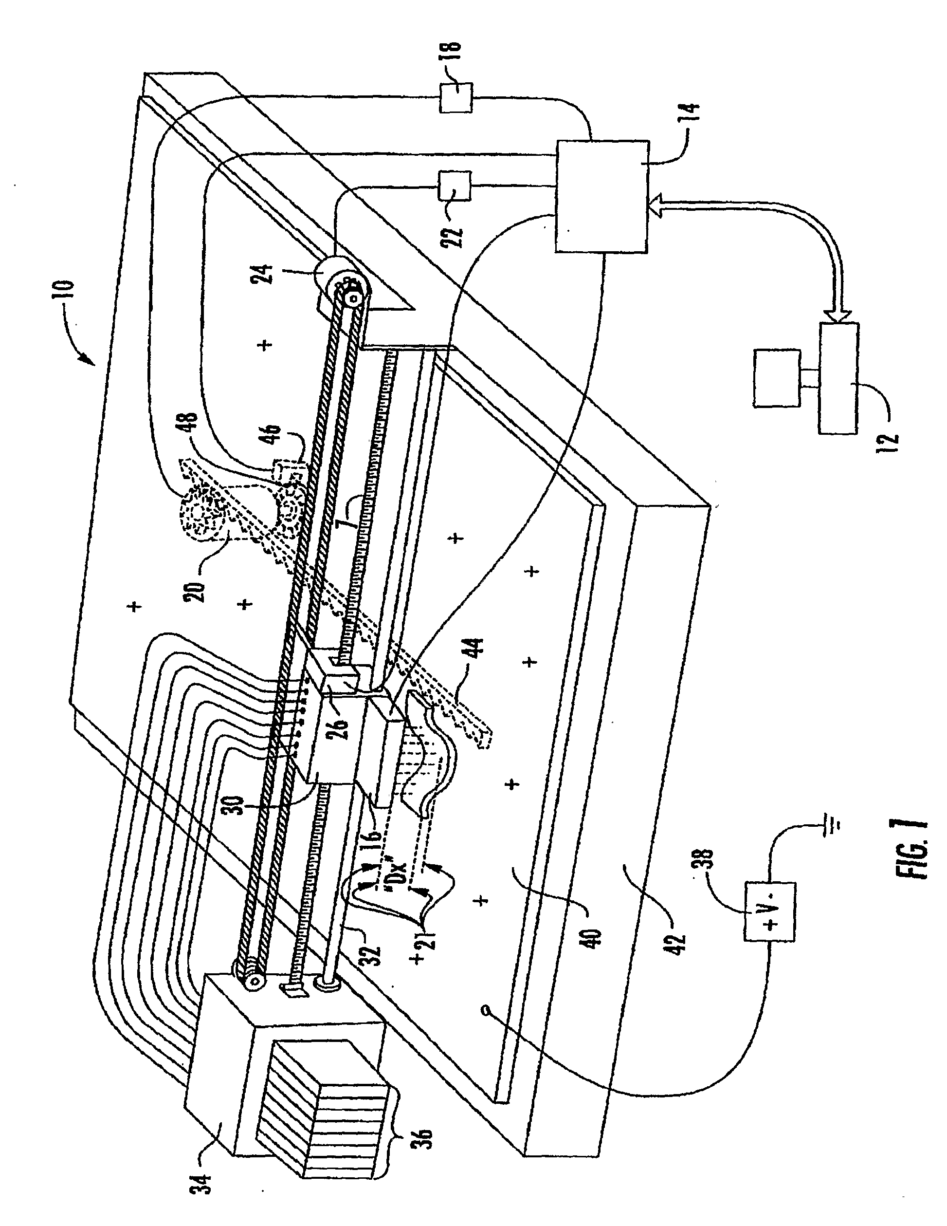
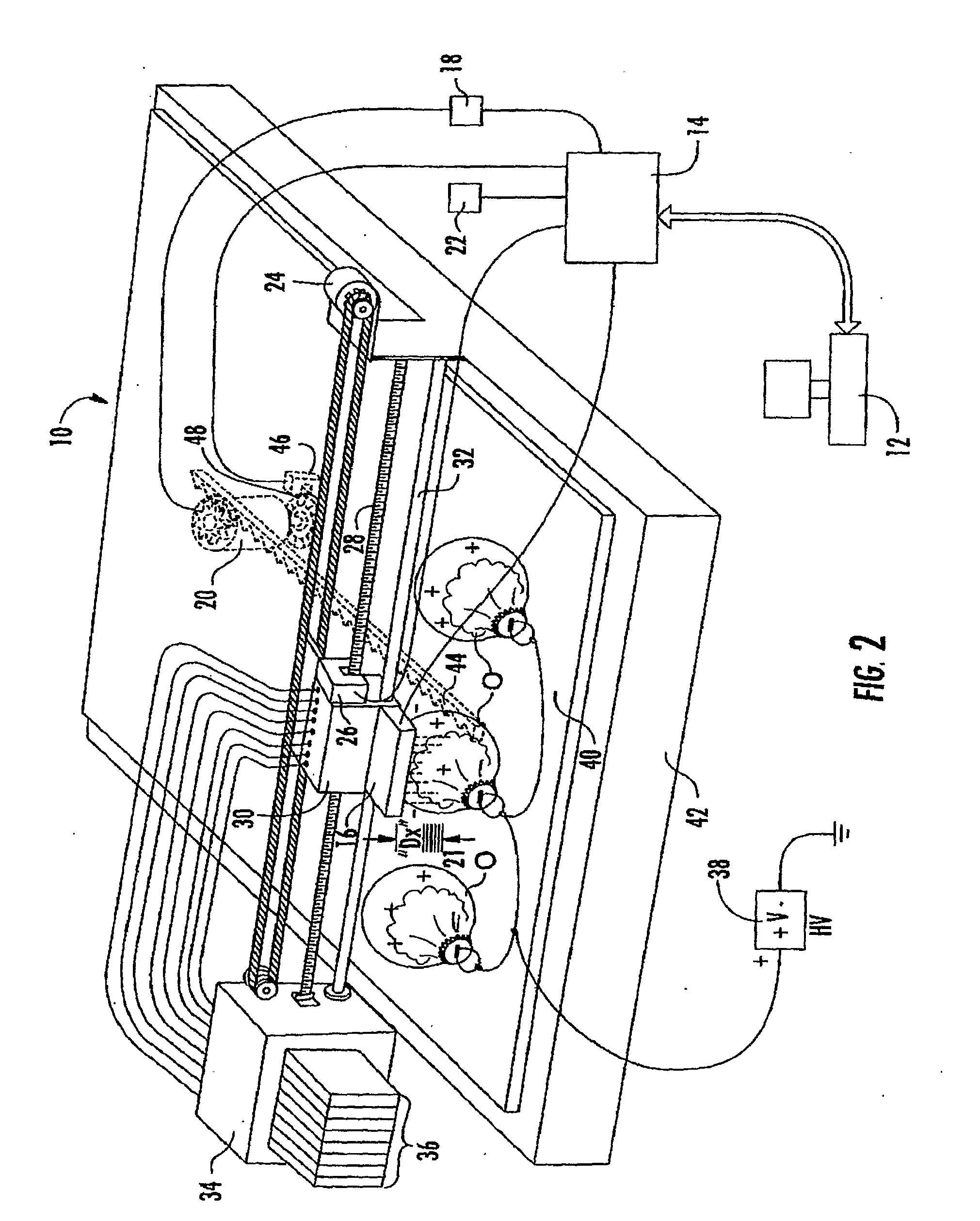
[0025]Referring now specifically to the drawings, an image printing system according to an embodiment of the invention is illustrated in FIG. 1 and shown generally at reference numeral 10. The system 10 includes a computer 12 having image rendering software connected to a printer control board 14. The printer control board 14 includes electronic hardware and firmware for interpreting instructions from the computer 12 to control an ink jet print head 16. The printer control board 14 also provides signals to a platen advance motor driver 18 to control a platen motor 20 and a carriage motor driver 22 to control a carriage motor 24.

[0026]A carriage encoder sensor 26 interacts with the printer control board 14 and a carriage encoder strip 28 to provide accurate indication of the location of a carriage assembly 30. The carriage assembly 30 is supported by a carriage support rail 32 and is driven by the carriage motor 24. The carriage assembly 30 includes ink dampeners, a print head 16, an...


PUM


Abstract

An apparatus for printing an image on an object that includes electronic image storage for storing an image to be printed on a image surface of the object, and a print head positioned in spaced-apart relation to the object for receiving electronic data representing the image to be printed through the ink jet print head and applying the image to object using an ink that is applied with a predetermined electrical charge polarity. A voltage generator generates an electrical charge having an opposite polarity charge in relation to the predetermined charge polarity of the ink, and applies the opposite charge proximate the object and at a position to accelerate the ink being applied from the print head onto the object.

Description

TECHNICAL FIELD AND BACKGROUND OF THE INVENTION[0001]The present invention relates to the field of image printing systems. In particular, the invention relates to an image printing apparatus and method capable of printing images on flat, curved, spherical, regular and irregular substrates.[0002]Currently, there are several methods being used to print images on flat and irregular surfaces. However, these methods do not address the issue of varying distances between the substrates to be printed and print head; rather, they attempt to maintain a constant distance by curving the travel of the print head relative to the curvature of the substrate, or by moving the substrate during ink projection to maintain this distance. Additionally, these methods do not compensate for droplet loss due to droplets that are directed away from the substrate, causing density loss and an image that is out-of-focus or slightly fuzzy.[0003]Thus, it is desirable to provide an image printing system and method ...

Claims


Application Information

Patent Timeline
Patent Type & Authority Applications(United States)
IPC IPC(8): B41J29/38B41J2/06
CPCB41J3/4073B41J3/40731
Inventor POLK, MICHAEL LANECOPELAND, KEITH HUBERT
Owner SAIN TODD
Learn More