Method and apparatus for printing images

a printing method and image technology, applied in printing presses, typewriters, printing, etc., can solve the problems of inconvenient image printing, inconvenient operation, and inability to address the problem of varying distances, and achieve the effect of accurate and clear image printing

Inactive Publication Date: 2010-07-29
SAIN TODD
View PDF24 Cites 42 Cited by
  • Summary
  • Abstract
  • Description
  • Claims
  • Application Information

AI Technical Summary

Benefits of technology

[0006]It is another object of the invention to provide an image printing system that permits accurate, clear application of images on flat, curved, spherical, regular and irregular substrates.
[0007]It is another object of the invention to provide an image printing system that controls droplet rebound during image creation.
[0008]These and other objects of the present invention are achieved in the preferred embodiments disclosed below by providing a tray for holding at least one object while an image is printed on a predetermined exposed portion of the object. The tray includes at least one object retainer carried by the tray and for positioning the object in a stationary condition in relation to the tray during printing. A panel is carried by the tray and has at least one opening positioned in relation to the object retainer such that the exposed portion of the object is exposed to ink projected onto the object from an ink-projecting apparatus positioned in spaced-apart relation to the object. An indexer is carried by the tray for permitting relative movement between the tray and the ink-projecting apparatus as the image is printed on the exposed portion of the object.

Problems solved by technology

However, these methods do not address the issue of varying distances between the surfaces to be printed and the print head; rather, they attempt to maintain a constant distance by curving the travel of the print head relative to the curvature of the substrate, or by moving the substrate during ink projection to maintain this distance.
Additionally, these methods do not compensate for droplet loss due to droplets that are directed away from the substrate, causing density loss and an image that is out-of-focus or slightly fuzzy.
Furthermore, overspray from an ink print head may cause a less than desirable image print.

Method used


Image

  • Method and apparatus for printing images
  • Method and apparatus for printing images
  • Method and apparatus for printing images

Examples


Embodiment Construction

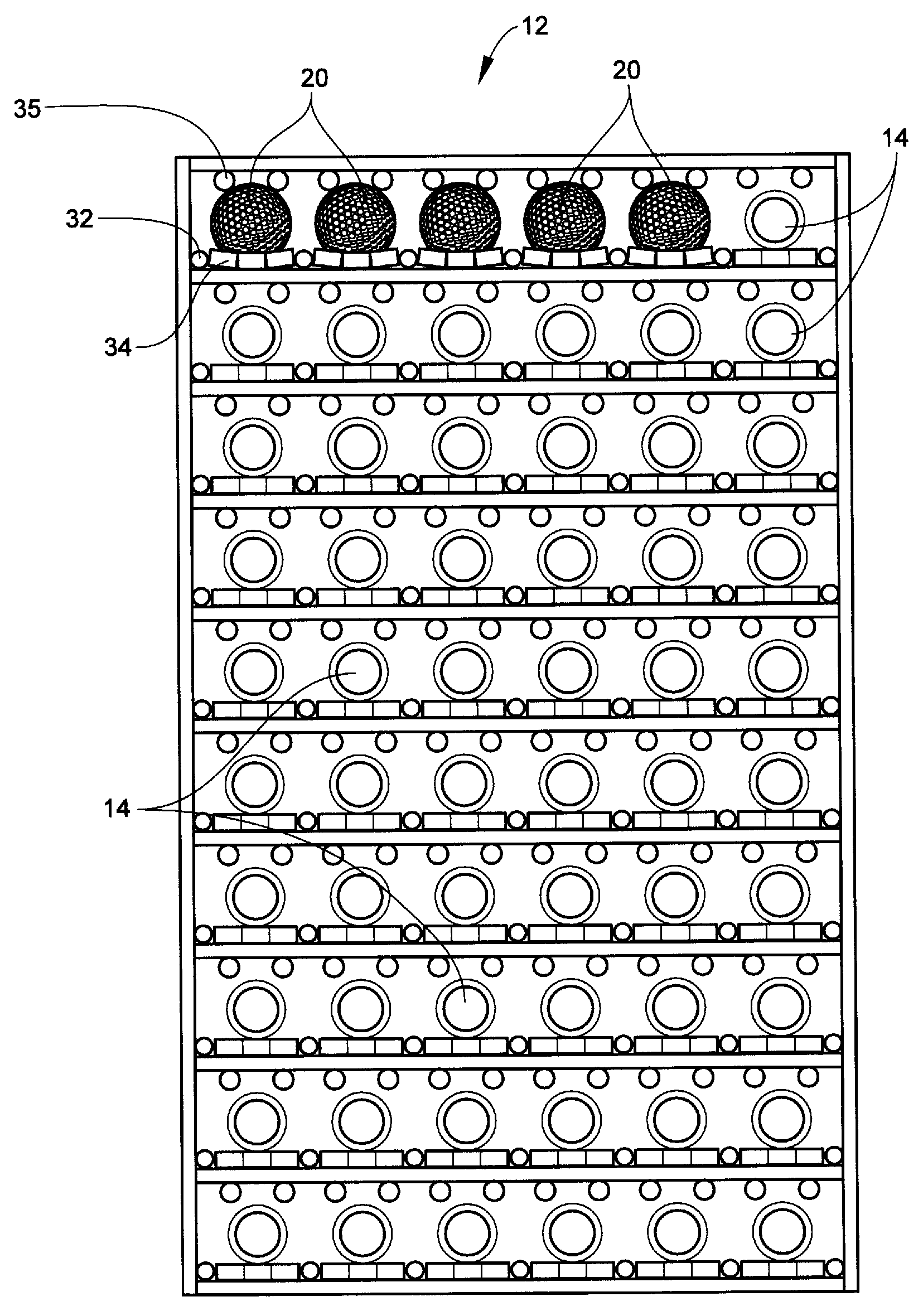
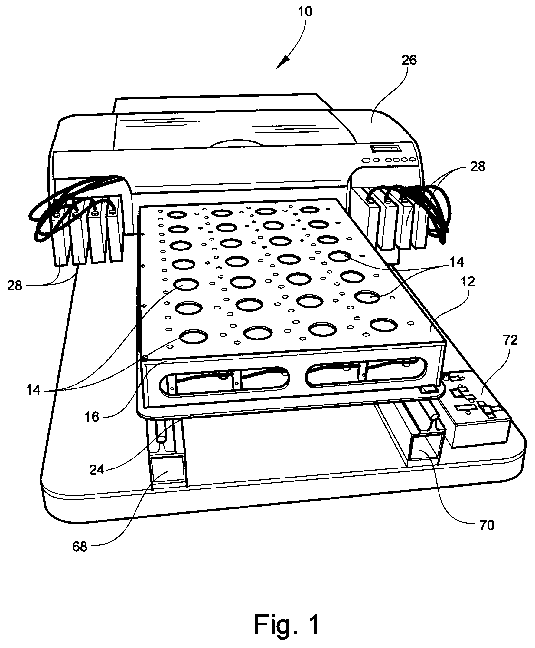
[0032]Referring now specifically to the drawings, an image printing system according to an embodiment of the invention is illustrated in FIG. 1 and shown generally at reference numeral 10. The printing system 10 includes a printer 26 and ink supply 28. The ink supply 28 includes different colors of ink and is suitable for an operator's desired use. A tray 12 is provided and configured to slide underneath the printer 26 by a conveyor system 67 formed by a pair of spaced apart and generally parallel rails 68 and 70 mounted on a platen support 66. The rails 68, 70 are designed such that the tray 12 is able to slide underneath the printer 26 in response to a mechanical input designed to impart linear movement to the tray 12. Any means that will impart movement to the tray 12 may be used. Examples include a linear actuator, conveyor track, and / or automated robotic system designed to slide the tray 12. A controller system 72 is suitably attached to control the electrical components of the...


PUM


Abstract

A tray for holding at least one object while an image is printed on a predetermined exposed portion of the object, including at least one object retainer carried by the tray and for positioning the object in a stationary condition in relation to the tray during printing, a panel carried by the tray and having at least one opening positioned in relation to the object retainer such that the exposed portion of the object is exposed to ink projected onto the object from an ink-projecting apparatus positioned in spaced-apart relation to the object, and an indexer carried by the tray for permitting relative movement between the tray and the ink-projecting apparatus as the image is printed on the exposed portion of the object.

Description

TECHNICAL FIELD AND BACKGROUND OF THE INVENTION[0001]The present invention relates to the field of image printing systems. In particular, the invention relates to an image printing apparatus and method capable of printing images on curved and spherical substrates.[0002]Currently, there are several methods being used to print images on the surfaces of objects. Typically, these methods incorporate a printer spaced apart from a tray holding of plurality of objects. However, these methods do not address the issue of varying distances between the surfaces to be printed and the print head; rather, they attempt to maintain a constant distance by curving the travel of the print head relative to the curvature of the substrate, or by moving the substrate during ink projection to maintain this distance. Additionally, these methods do not compensate for droplet loss due to droplets that are directed away from the substrate, causing density loss and an image that is out-of-focus or slightly fuzz...

Claims


Application Information

Patent Timeline
Patent Type & Authority Applications(United States)
IPC IPC(8): B41J17/00
CPCB41J3/407B41J3/4073B41J3/40731
Inventor POLK, MICHAEL LANEFRANKLIN, GREGORY L.
Owner SAIN TODD
Why Eureka
Try Eureka