Closet flange system for existing installation

a technology for closet flanges and existing installations, applied in the field of closet flanges, can solve the problems of not permitting a direct connection between a toilet and the closet flange, and requiring unfavorable installation of closet flanges

Active Publication Date: 2010-02-18
OATEY CO
View PDF59 Cites 32 Cited by
  • Summary
  • Abstract
  • Description
  • Claims
  • Application Information

AI Technical Summary

Benefits of technology

[0007]A system is provided herein which includes a closet flange insert and at least one spacer to be positioned between the closet flange insert and an installed closet flange. The closet flange insert includes a toilet connecting flange which extends radially outwardly from a through pipe. The through pipe is sized to be inserted into a pipe section of a closet flange. Each spacer includes spaced apart first and second faces, and spaced apart inner and outer edges extending between the first and sec

Problems solved by technology

With the closet flange fixed to the sub-flooring, however, the finished flooring extends above the closet flange, thus not permitting a direct connection between a toilet and the closet flange.
However, the scrap material spacers often either do not provide sufficient elevation to accommodate the thickness of the finished flooring, thus not permit

Method used


Image

  • Closet flange system for existing installation
  • Closet flange system for existing installation
  • Closet flange system for existing installation

Examples


Embodiment Construction

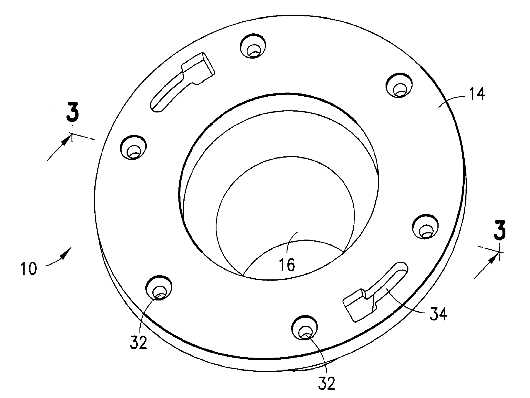
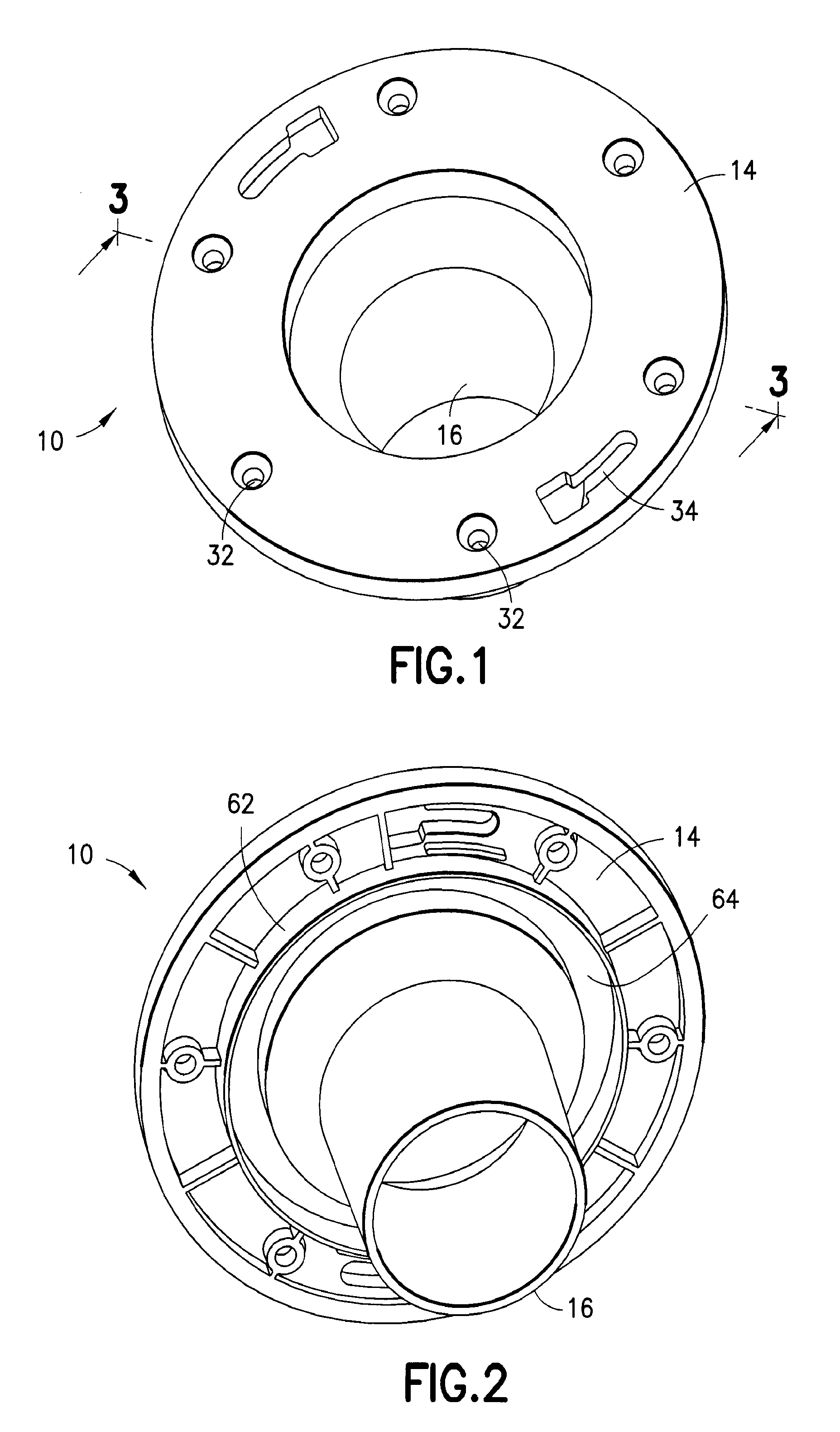
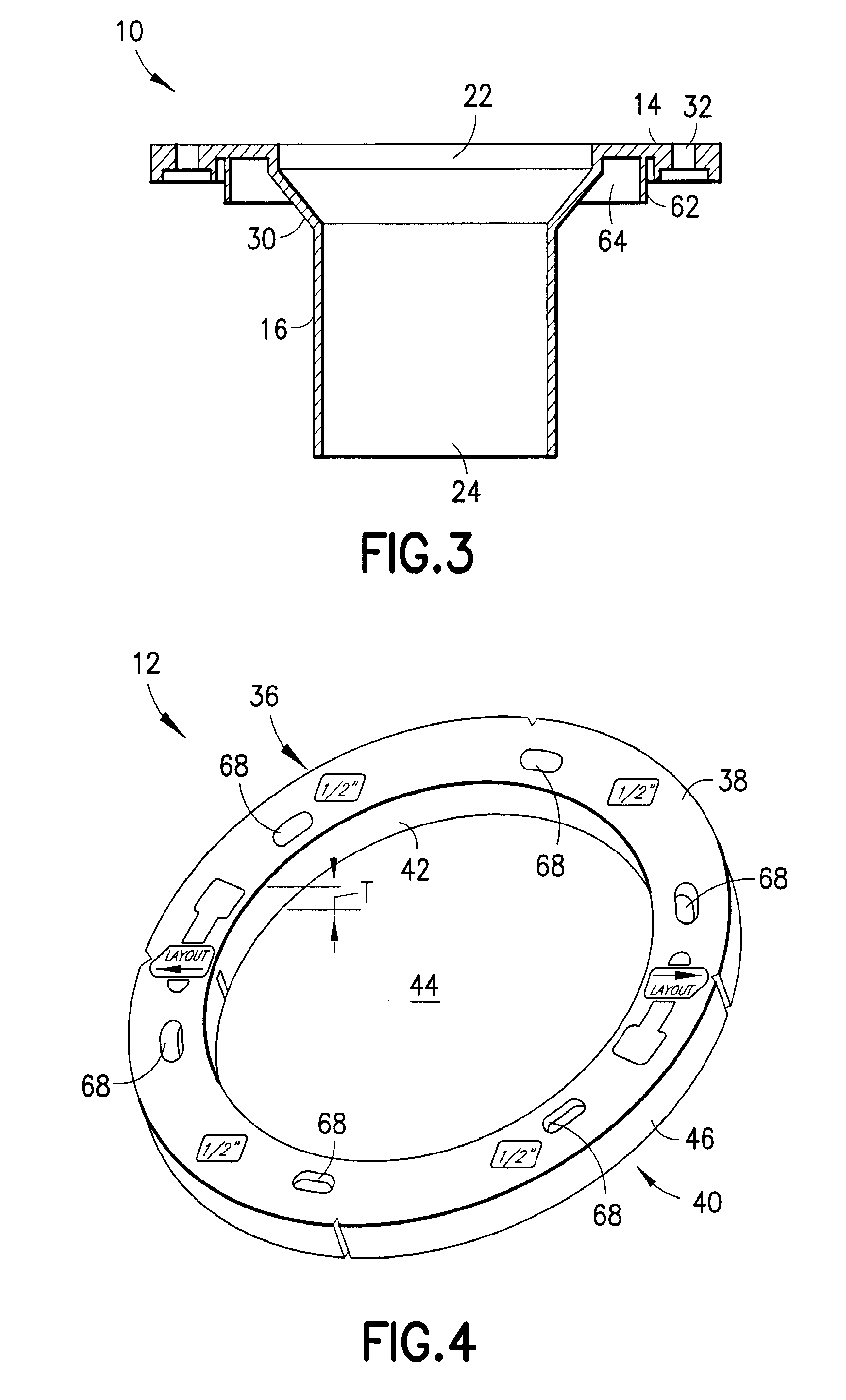
[0014]A system is provided herein which includes a closet flange insert 10 and at least one spacer 12. The spacer(s) 12 are formed in accordance with the disclosure of U.S. patent application Ser. No. 11 / 269,022, published as U.S. Published Patent Application No. 2006 / 0213003 A1, and PCT International Application No. PCT / US2006 / 10669, published as PCT Published Patent Application No. WO 2006 / 104861. The disclosures of these references are incorporated by reference herein.

[0015]The closet flange insert 10 includes an annular flange 14 extending from a through pipe 16. The through pipe 16 is formed with an outer diameter sized to fit within, and telescope into, a pipe section 18 of a closet flange 20 (FIG. 5). Standard closet flanges typically come in 3 inch or 4 inch diameters. The subject invention may be sized to these standard sizes or to other sizes. The through pipe 16 extends between an inlet opening 22, formed in the flange 14 and at least partially circumscribed thereby, and ...


PUM

PropertyMeasurementUnit
Diameteraaaaaaaaaa
Shapeaaaaaaaaaa

Abstract

A system is provided herein which includes a closet flange insert and at least one spacer to be positioned between the closet flange insert and an installed closet flange. The closet flange insert includes a toilet connecting flange which extends radially outwardly from a through pipe. The through pipe is sized to be inserted into a pipe section of a closet flange. Each spacer includes spaced apart first and second faces, and spaced apart inner and outer edges extending between the first and second faces. The inner edge defines an opening extending through the body, the opening sized to permit passage therethrough of the through pipe of the closet flange insert but not the toilet connecting flange of the closet flange insert. Advantageously, with the subject invention, a system is provided which allows the closet flange insert to be mounted atop an installed closet flange, with one or more spacers therebetween, and with the closet flange insert being flush with surrounding finished flooring.

Description

CROSS-REFERENCE TO RELATED APPLICATION[0001]This application claims priority of U.S. Provisional Application No. 60 / 845,851, filed Sep. 20, 2006, the entire contents of which are hereby incorporated by reference.BACKGROUND OF THE INVENTION[0002]With new building construction or renovation, a closet flange is typically installed prior to installation of finished flooring. To do so, a hole is made through the sub-flooring at a desired location for a toilet. The hole is sized to accommodate a closet flange. There are, then, several options in the prior art to install a closet flange through the hole in the sub-flooring. In one option, a closet flange is directly fastened to the sub-flooring, and a finished flooring is installed about the closet flange. With the closet flange fixed to the sub-flooring, however, the finished flooring extends above the closet flange, thus not permitting a direct connection between a toilet and the closet flange. To allow for a proper sealed connection, cl...

Claims


Application Information

Patent Timeline
IPC IPC(8): E03D11/16
CPCY10T29/49826E03D11/16
Inventor HUGHES, ALAN
Owner OATEY CO
Why Eureka
Try Eureka