Surface Treatments And Coatings For Flash Atomization

a technology of surface treatment and coating, which is applied in the direction of combustible gas purification/modification, lighting and heating apparatus, and separation processes, etc., can solve the problems of high heat and pressure required to flash vaporize the fluid, and achieve the effect of reducing the heat and pressur

Active Publication Date: 2010-03-04
GENERAL ELECTRIC CO
View PDF40 Cites 5 Cited by
  • Summary
  • Abstract
  • Description
  • Claims
  • Application Information

AI Technical Summary

Problems solved by technology

The heat and pressure required to flash vaporize the fluid can be very high for a ...

Method used


Image

  • Surface Treatments And Coatings For Flash Atomization
  • Surface Treatments And Coatings For Flash Atomization
  • Surface Treatments And Coatings For Flash Atomization

Examples


Embodiment Construction

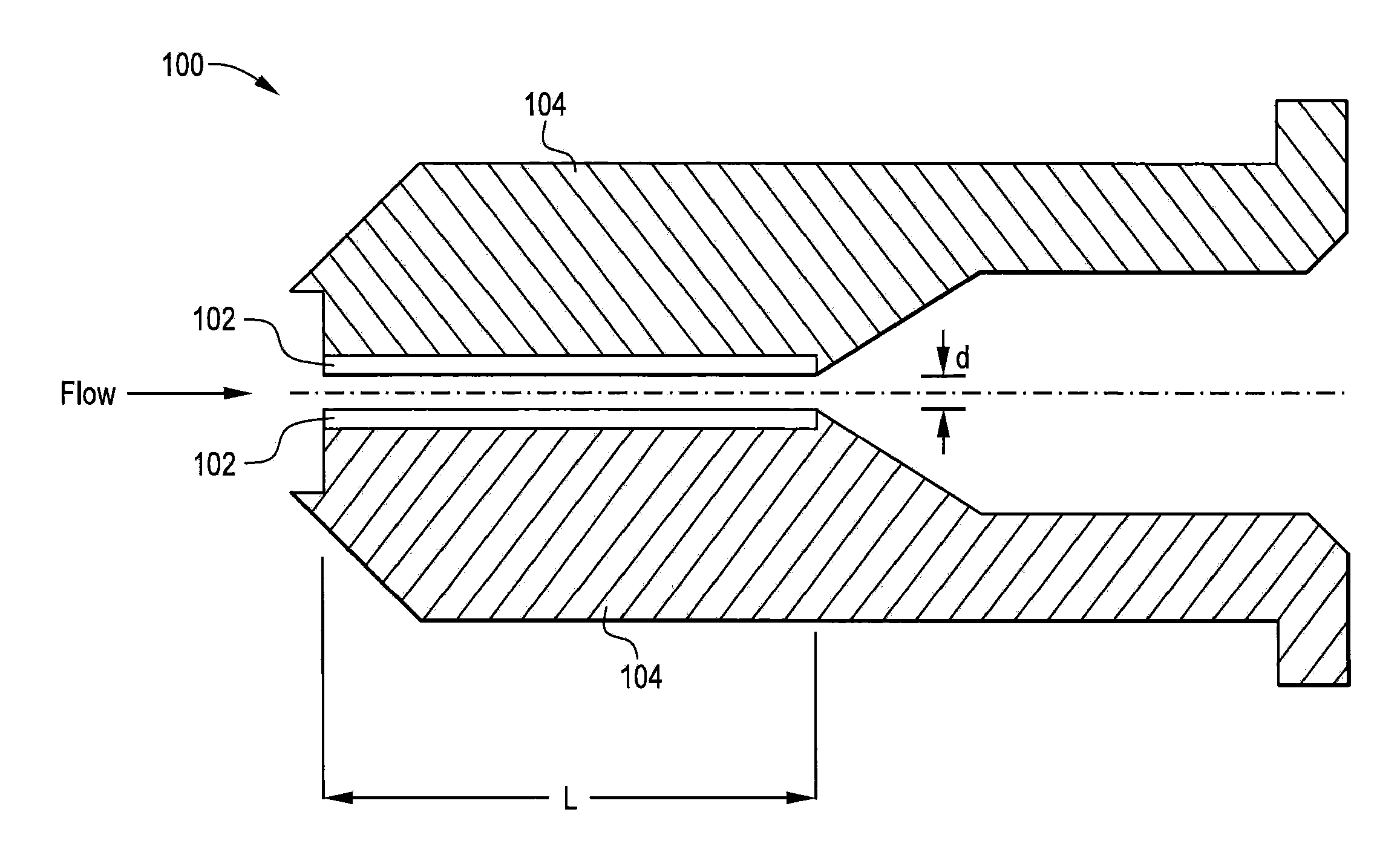
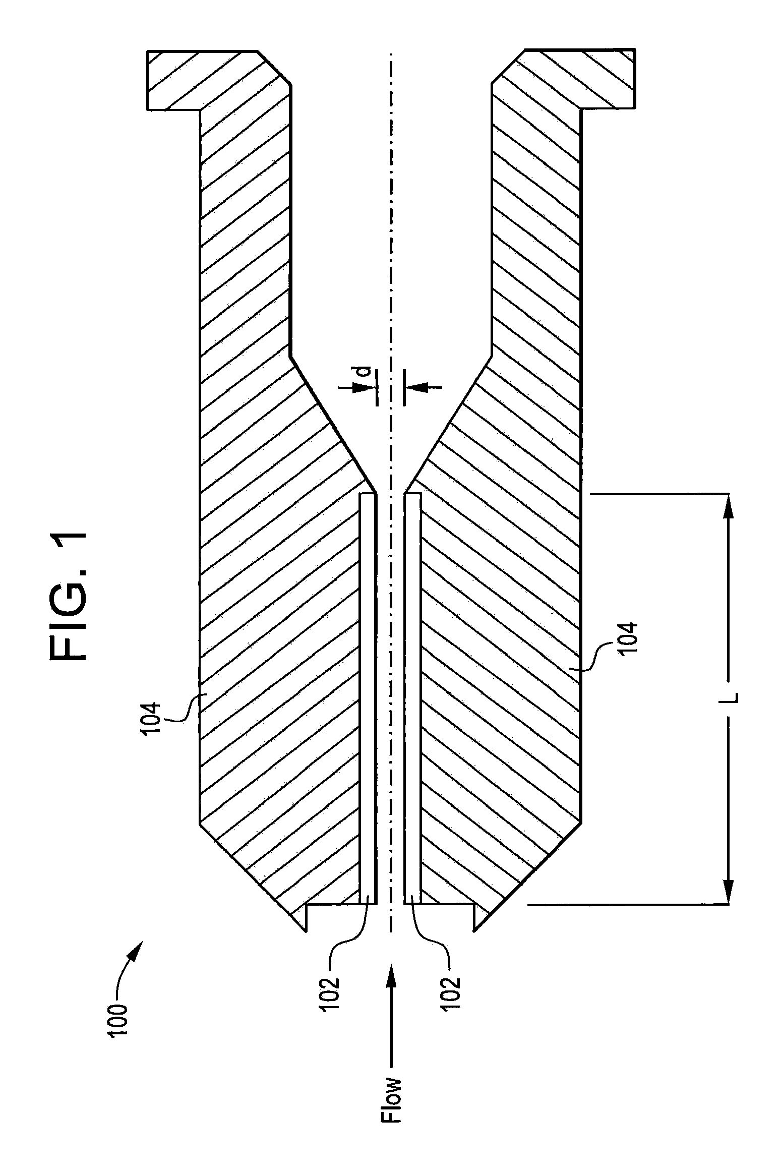
[0011]The flash atomizers and flash atomization systems described herein include an enhanced surface to reduce the superheat and pressure required to produce a two-phase flow regime in the atomizer channel or orifice. The superheat and pressure can be reduced compared to current flash atomizers and systems that utilize smooth channel, and orifice or untreated surfaces. The enhanced surfaces described herein are configured to reduce the superheat required for boiling incipience (i.e., initial bubble nucleation of the liquid). The enhanced surfaces also can increase vapor generation for a given superheat relative to the smooth surfaces of current flash atomizers, because the enhanced surfaces comprise far more active nucleation sites of controllable size and distribution than the current atomizer surfaces. Moreover, a flash atomizer comprising the enhanced surfaces can generate very small uniform droplets with a reduced channel length-to-hydraulic diameter ratio (L / dh), and at a reduc...


PUM

PropertyMeasurementUnit
Lengthaaaaaaaaaa
Lengthaaaaaaaaaa
Fractionaaaaaaaaaa

Abstract

A flash atomizer comprising a channel substrate configured to generate a vapor and form a two-phase flow of a fluid; and an enhanced surface disposed on the channel substrate and configured to change a temperature and a pressure required to form the vapor, wherein the enhanced surface texture comprises a plurality of active nucleation sites configured to promote heterogeneous bubble nucleation.

Description

BACKGROUND OF THE INVENTION[0001]The present disclosure relates to surfaces and coatings for flash atomization, and more particularly, relates to incorporating enhanced surface technologies to improve flash atomization.[0002]Atomization generally refers to the conversion of bulk liquid into a spray or mist (i.e. collection of drops), often by passing the liquid through a nozzle. An atomizer is an apparatus for achieving atomization. Common examples of atomization systems can include: gas turbines, carburetors, airbrushes, misters, spray bottles, and the like. In internal combustion engines for example, fine-grained fuel atomization can be instrumental to efficient combustion.[0003]Current air-blast atomizers spread liquid from a nozzle orifice into a film on one or more pre-filming regions. The atomizers can use pressure, airflow, electrostatic, ultrasonic, and other like methods to create instabilities in the bulk liquid film to form droplets. Flash atomizers have been shown to pro...

Claims


Application Information

Patent Timeline
IPC IPC(8): F02M17/18B01D53/56B01D53/92F02M19/03B01F25/70
CPCB05B1/24F01N2610/1453B05B17/04B05B9/005
Inventor SWANSON, LARRY WILLIAM
Owner GENERAL ELECTRIC CO
Why Eureka
Try Eureka