Fuel cell system and fuel supply method thereof

a fuel cell and system technology, applied in the energy industry, basic electric elements, electric generating devices, etc., can solve the problems of unstable concentration of carbon monoxide, inability to determine the stable and efficient specification of the fuel pump, and failure of flames, so as to achieve efficient and stable fuel cell system operation.

Inactive Publication Date: 2010-03-11
SAMSUNG ELECTRONICS CO LTD
View PDF24 Cites 4 Cited by
  • Summary
  • Abstract
  • Description
  • Claims
  • Application Information

AI Technical Summary

Benefits of technology

[0008]The present invention has been made in view of the above-mentioned problems, and an aspect of the present invention is to provide a fuel supply device and a fuel supply method in a fuel cell system, which are capable of automating an S / C control and a lamda control, and achieving a fuel cell system operation efficiently and stably coping with pressure loss and pulsation occurring within the system, while using a minimum number of balance-of-plant (BOP) units for the supply of reformer fuel and burner fuel.

Problems solved by technology

For this reason, in the case of a particular BOP unit, for example, the fuel pump, it is impossible to determine the stable and efficient specification of the fuel pump.
In this case, a flame may fail.
Also, the concentration of carbon monoxide may be unstable.
As a result, an imperfect operation condition may occur.
However, this is non-economical in terms of costs.

Method used


Image

  • Fuel cell system and fuel supply method thereof
  • Fuel cell system and fuel supply method thereof
  • Fuel cell system and fuel supply method thereof

Examples


Embodiment Construction

[0050]Reference will now be made in detail to the embodiments of the present invention, examples of which are illustrated in the accompanying drawings, wherein like reference numerals refer to the like elements throughout. The embodiments are described below to explain the present invention by referring to the figures.

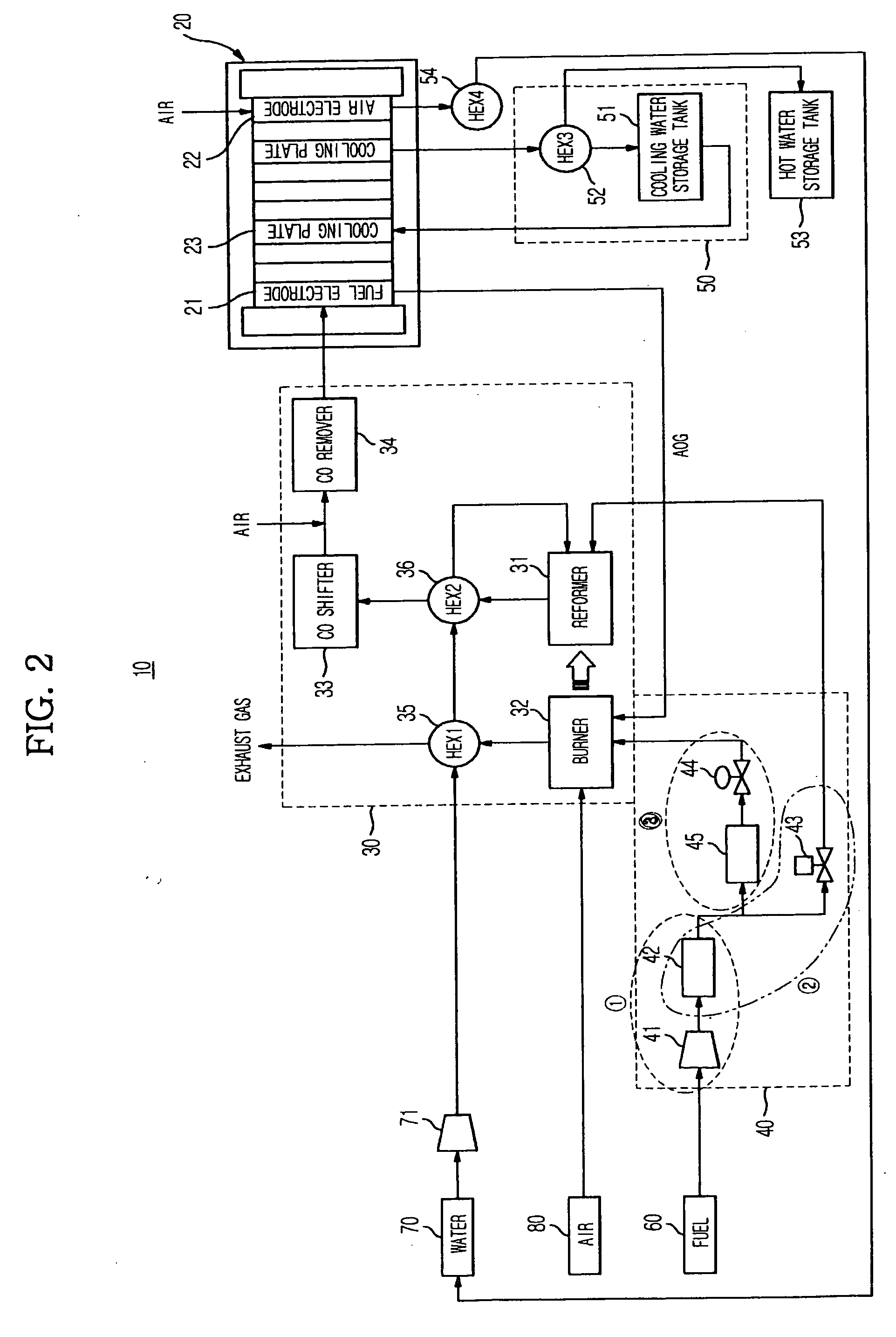
[0051]FIG. 2 is a block diagram illustrating a fuel cell system according to an embodiment of the present invention.

[0052]Referring to FIG. 2, the fuel cell system 10 according to the illustrated embodiment of the present invention includes a stack 20 to generate electricity, a fuel treating unit 30 to produce hydrogen to be supplied to the stack 20, a fuel supplying unit 40 to supply fuel 60 to the fuel treating unit 30, a cooling unit 50 to cool the stack 20, and balance-of-plant (BOP) units.

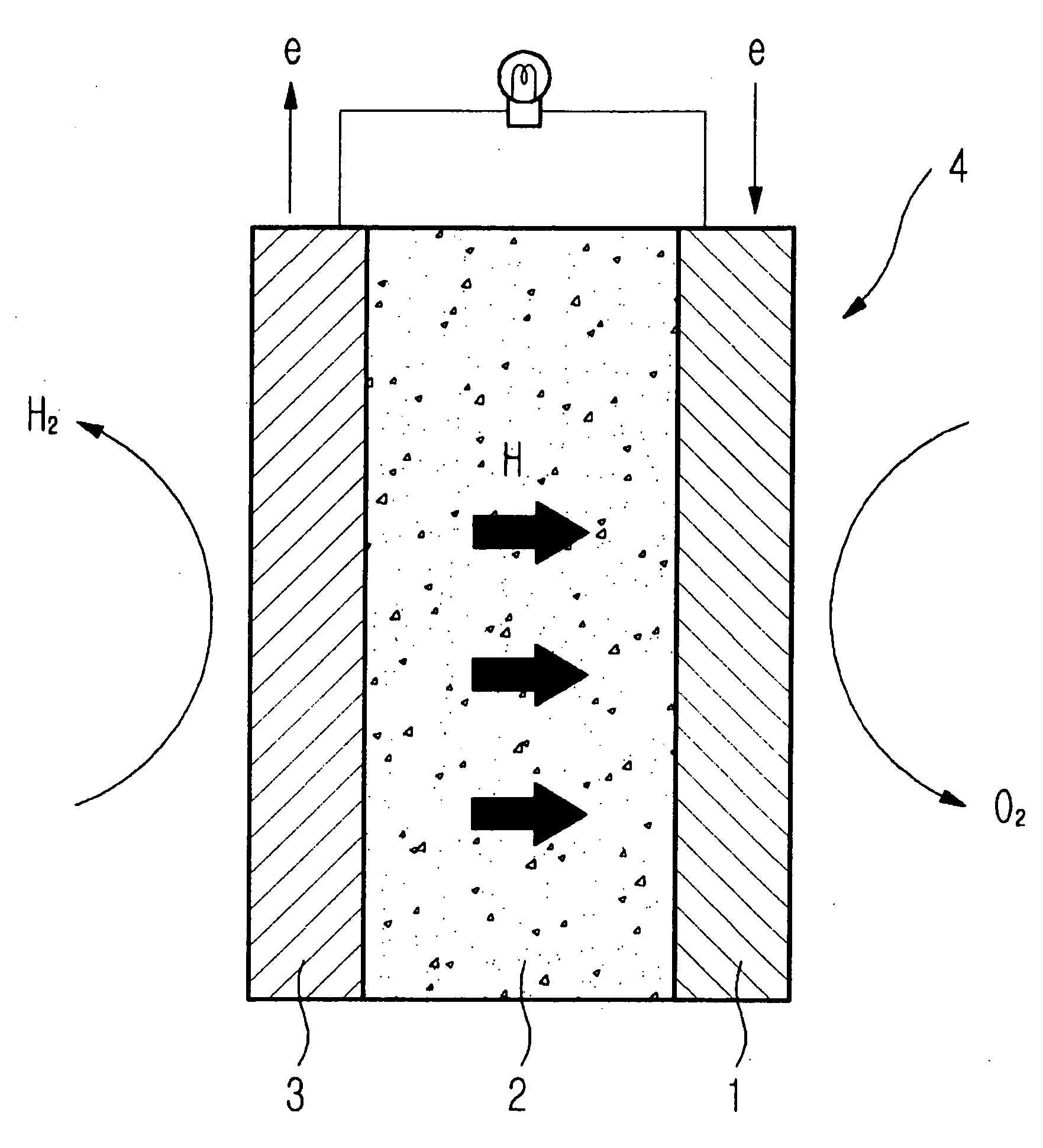
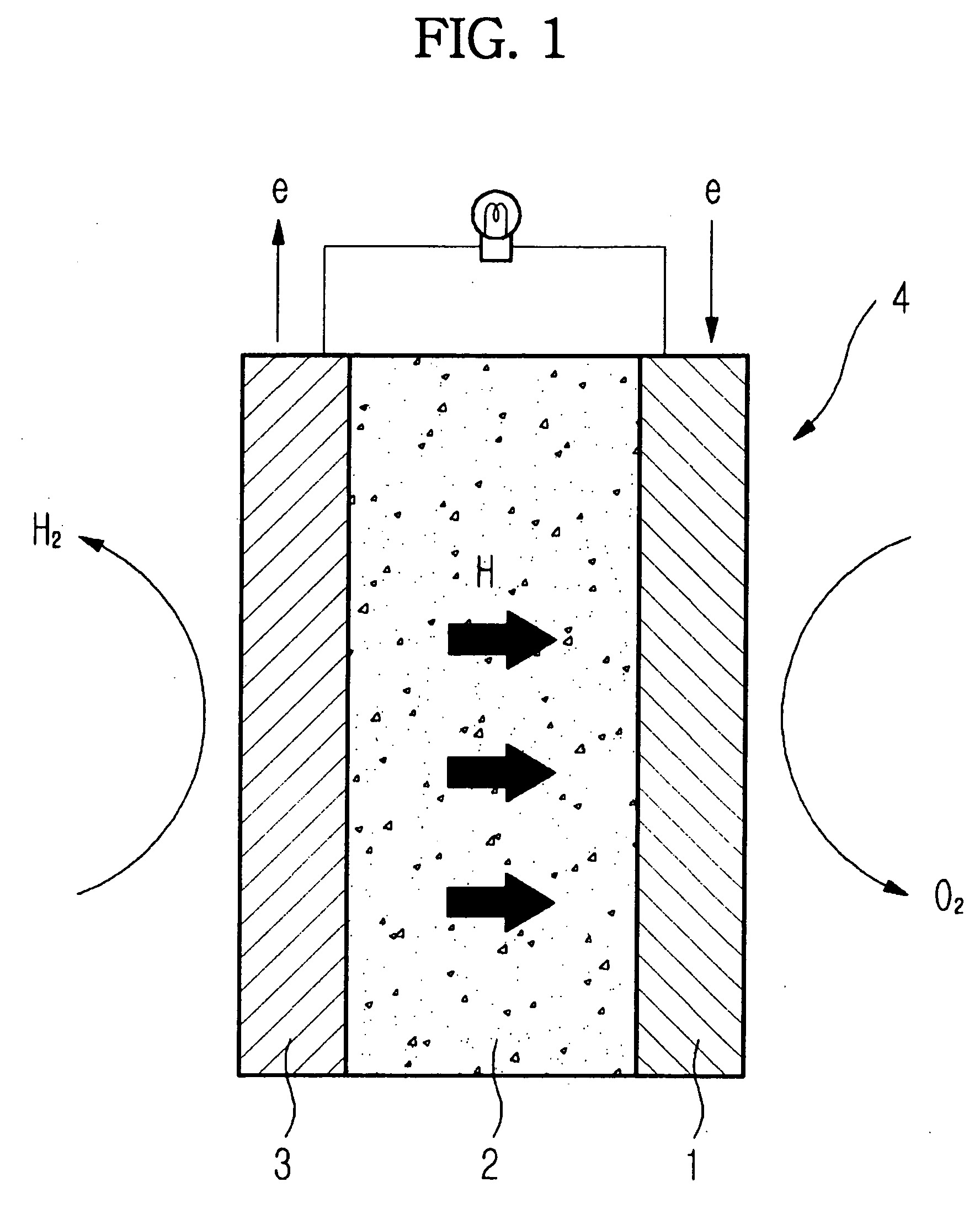
[0053]The stack 20 is an electricity generating device to directly convert chemical energy of hydrogen and oxygen contained in the fuel 60, namely, hydrocarbon-based fuel such as...


PUM

PropertyMeasurementUnit
temperatureaaaaaaaaaa
energyaaaaaaaaaa

Abstract

A stable fuel supply system in a fuel cell system produces heat and electricity by combining hydrogen modified from a major raw material selected from various hydrogen compounds, with oxygen existing in air. A fuel supply device and a fuel supply method in a fuel cell system, which automate a steam to carbon ratio (S/C) control and a lamda control, and achieve a fuel cell system operation efficiently and stably coping with pressure loss and pulsation occurring within the system, while using a minimum number of balance-of-plant (BOP) units. A method more efficiently and precisely supplies fuel during the start-up and operation of the fuel cell system, while preventing flame failure of a burner and maintaining an appropriate carbon monoxide concentration even when an abrupt flow rate variation occurs. Also, an operating method improves functions associated with a decomposition ability based on selection of the specification of a fuel pump, and thus, is more economical and stable in terms of the costs and configuration of the fuel cell system.

Description

CROSS-REFERENCE TO RELATED APPLICATIONS[0001]This application claims the benefit of Korean Patent Application No. 10-2008-88952, filed on Sep. 9, 2008 in the Korean Intellectual Property Office, the disclosures of which are incorporated herein by reference.BACKGROUND[0002]1. Field[0003]The present invention relates to a fuel cell system and a fuel supply method thereof, and, more particularly, to a fuel cell system and a fuel supply method thereof, which are capable of reducing pulsation of fuel supplied to a reformer and a burner, thereby stably supplying the fuel, and maintaining a desired ratio of the components of modifying gas supplied to a stack.[0004]2. Description of the Related Art[0005]Generally, a fuel cell is an electricity generating device to directly convert chemical energy of hydrogen and oxygen contained in hydrocarbon-based fuel such as methanol, ethanol, or natural gas into electrical energy in accordance with an electrochemical reaction. FIG. 1 is a schematic vie...

Claims


Application Information

Patent Timeline
Patent Type & Authority Applications(United States)
IPC IPC(8): H01M8/04H01M8/06
CPCH01M8/04089H01M8/04425Y02E60/50H01M8/04776H01M8/0618H01M8/04753Y02P80/15H01M8/04H01M8/24
Inventor HEO, JIN S.HIGASHI, TAKAMIOH, JAE HYUK
Owner SAMSUNG ELECTRONICS CO LTD
Why Eureka
Try Eureka