Chucking device for a disk

Inactive Publication Date: 2010-03-25
SAMSUNG ELECTRO MECHANICS CO LTD
View PDF3 Cites 3 Cited by
  • Summary
  • Abstract
  • Description
  • Claims
  • Application Information

AI Technical Summary

Benefits of technology

[0025]According to the chucking device for a disk of the present invention, the inclined face is provided on the portion of the chuck pin where the elastic force of the spring is applied so tha

Problems solved by technology

It is very difficult to obtain a reduction in the loading forc

Method used


Image

  • Chucking device for a disk
  • Chucking device for a disk
  • Chucking device for a disk

Examples


Embodiment Construction

[0032]Reference will now be made in greater detail to a chucking device for a disk according to preferred embodiments of the invention, examples of which are illustrated in the accompanying drawings.

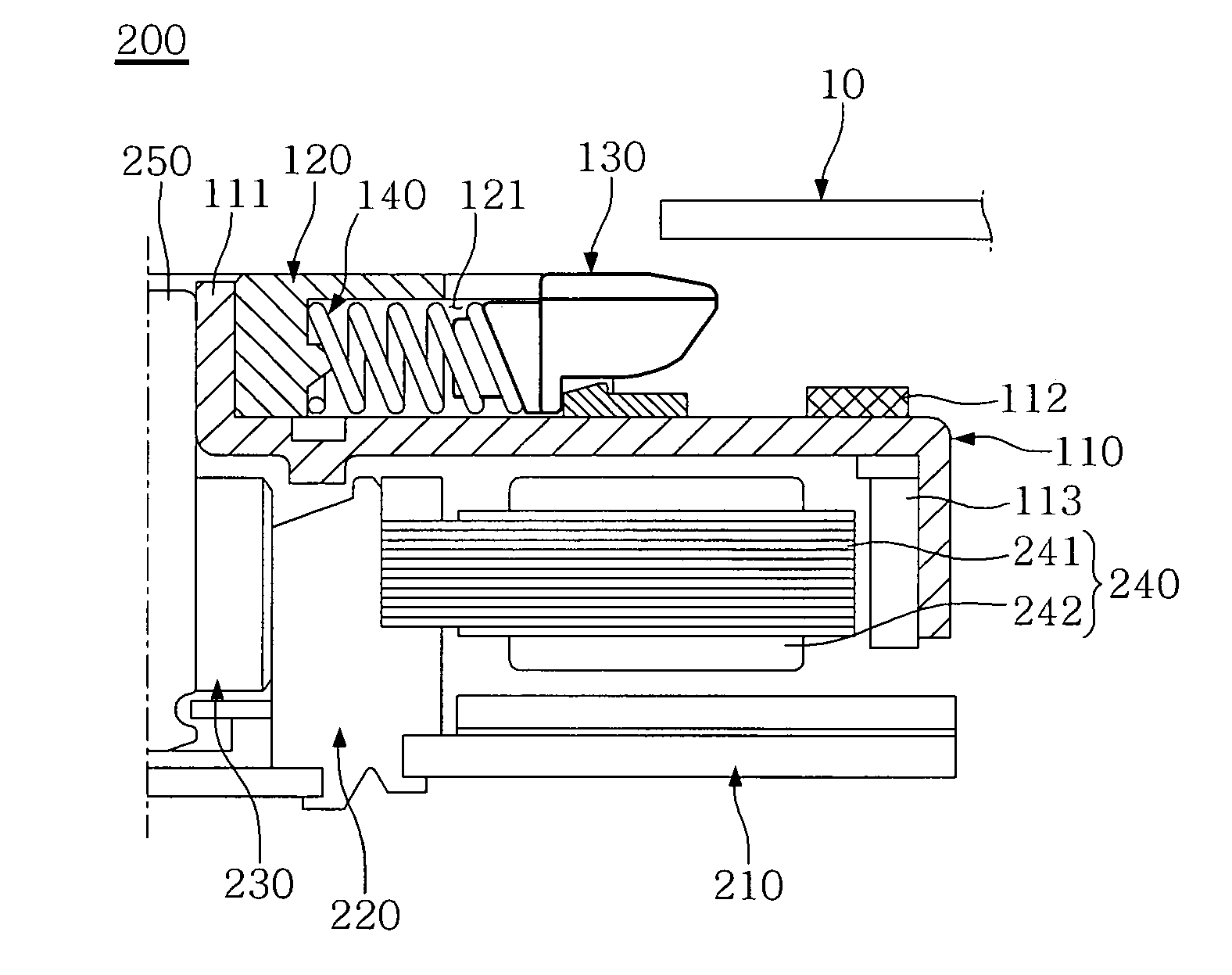
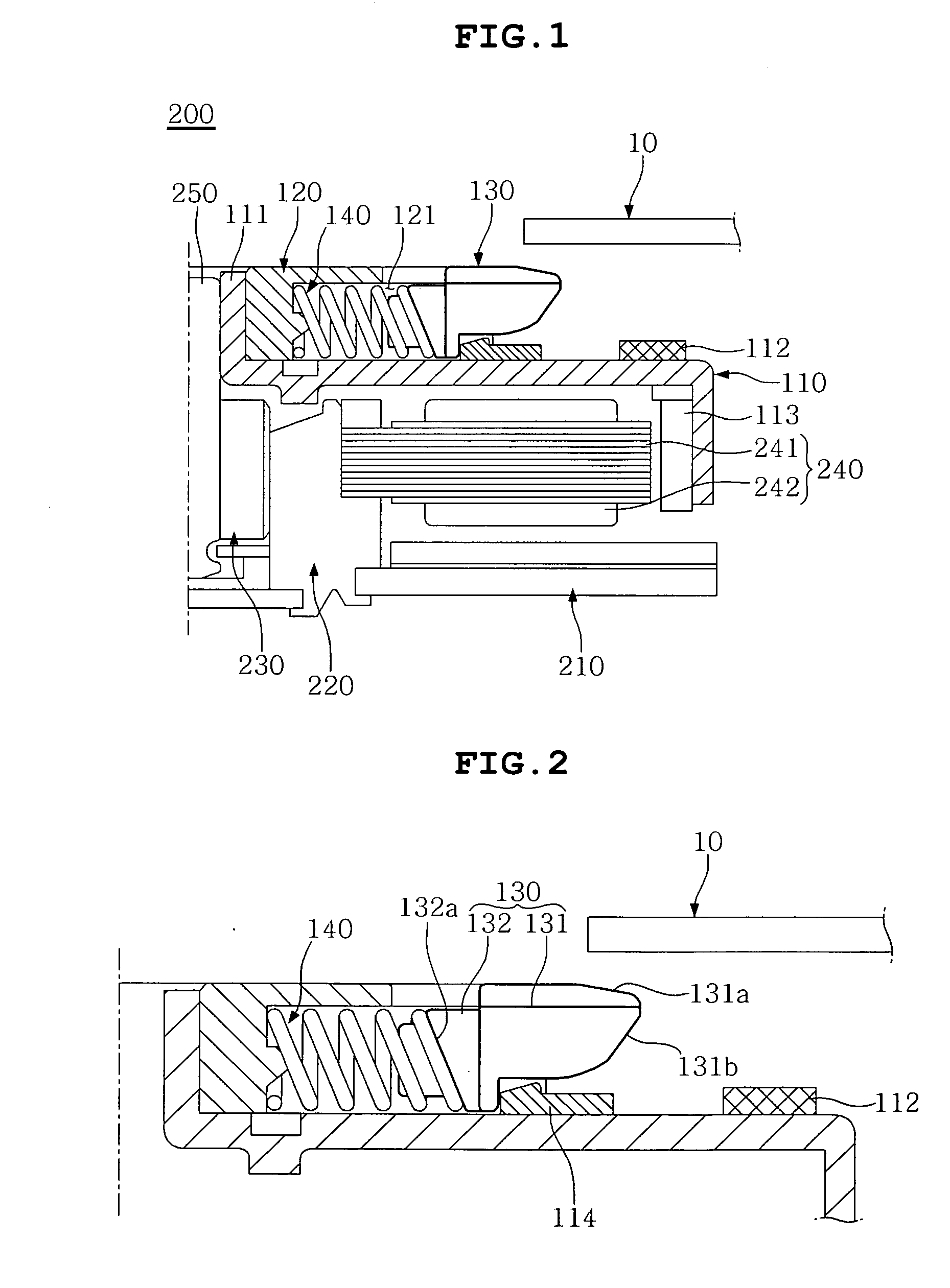
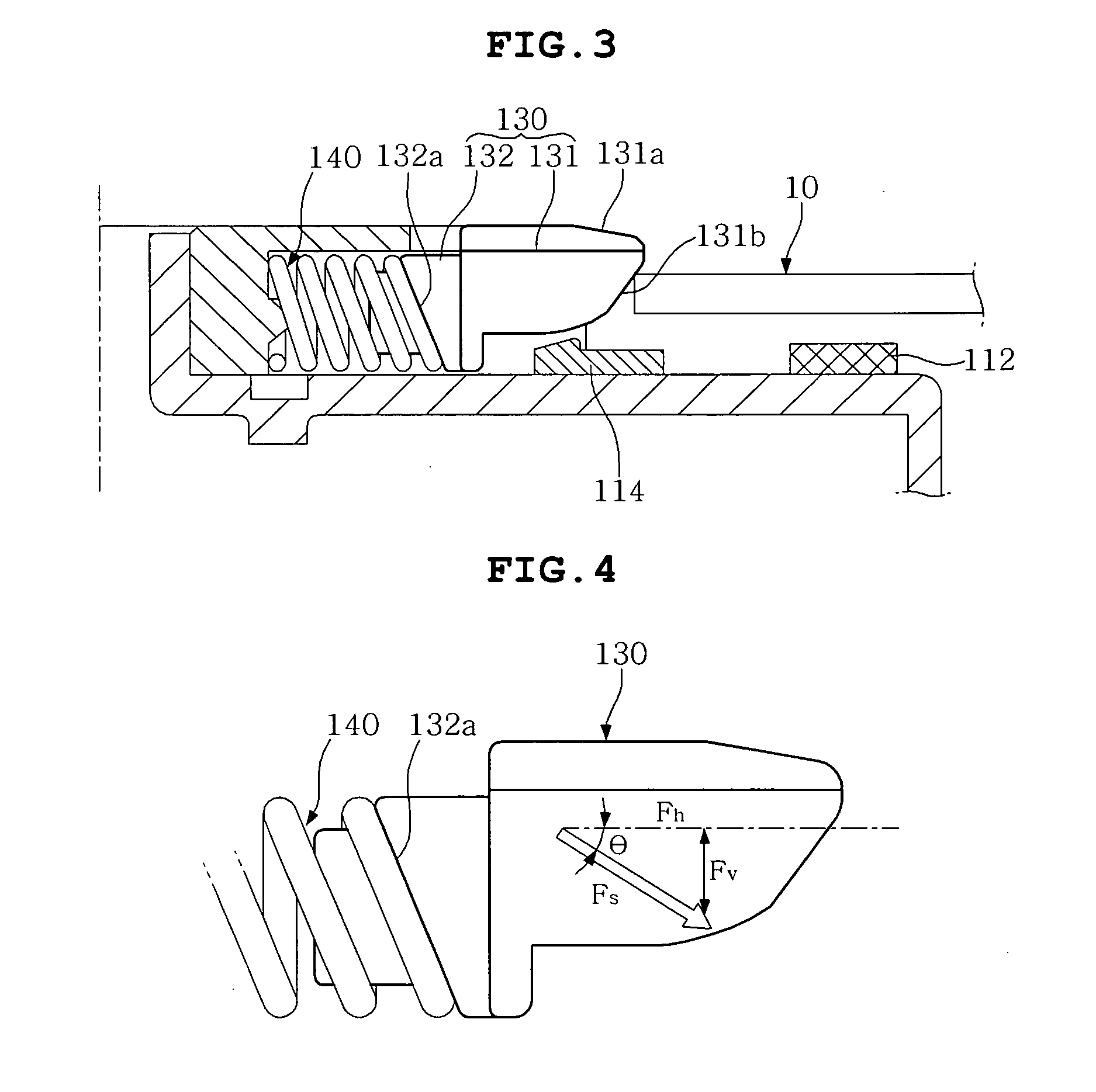
[0033]As illustrated in FIGS. 1 to 3, a chucking device 100 for a disk according to the invention is integrally installed on a spindle motor 200 so as to prevent deviation of an optical disk 10 when the spindle motor 200 rotates at high speed.

[0034]The spindle motor 200 is provided for loading and driving the optical disk 10, and includes a base 210, a bearing holder 220, a bearing 230, an armature 240, a rotating shaft 250, and a rotor case 110.

[0035]The base 210 is provided for supporting the whole of the spindle motor 200, and is fixedly installed on a device such as a hard disk driver or the like in which the spindle motor 200 is installed. The bearing holder 220 is of a hollow cylindrical shape so as to fixedly support the bearing 230, and an end thereof is calked or spun so that it...


PUM


Abstract

A chucking device for a disk including a turntable on which an optical disk is seated, a housing provided on the turntable in such a manner as to be inserted into a center hole of the optical disk, a chuck pin having an end protruding outwards from the housing so that, when the optical disk is inserted into and released from the chuck pin, the chuck pin reciprocates from the center of the optical disk, a spring elastically forcing the end of the chuck pin outwards from the center of the optical disk, and a spring holder provided slantwise on the chuck pin such that the spring is held thereon so that an elastic force of the spring is applied inclined onto the chuck pin acting towards the direction of the turntable.

Description

CROSS REFERENCE TO RELATED APPLICATION[0001]This application claims the benefit of Korean Patent Application No. 10-2008-0092677, filed on Sep. 22, 2008, entitled “Chucking Device for a Disk”, which is hereby incorporated by reference in its entirety into this application.BACKGROUND OF THE INVENTION[0002]1. Field of the Invention[0003]The present invention relates, in general, to a chucking device for a disk, and more particularly to a chucking device for a disk capable of increasing a chucking force for an optical disk while reducing a loading force for the optical disk.[0004]2. Description of the Related Art[0005]Generally, in an optical disk device for implementing a recording / reproducing operation on / from an optical disk such as compact disks (CDs), digital versatile disks (DVDs), blu-ray disks (BDs) or the like, a portable disk device has been widely developed in the related art as pertains to high density and high speed recording, reproducing and improvement in portability and...

Claims


Application Information

Patent Timeline
IPC IPC(8): G11B17/04
CPCG11B17/0282G11B17/028
Inventor YOO, YOUNG SUNCHOI, YEOLYOO, HO JUNSHIN, KYUNG SEOB
Owner SAMSUNG ELECTRO MECHANICS CO LTD
Why Eureka
Try Eureka