
Monitor Observation System and its Observation Control Method

a technology of monitor device and observation system, which is applied in the field of monitor device observation system and its observation control method, can solve the problems of inability to check the occurrence or not of an event outputted to the monitor device, the difficulty of concentrated observation, and the inability to perform the operation considerably inefficiently, so as to improve the convenience of users and the efficiency of observation work, the effect of quick check and quick deal

Inactive Publication Date: 2010-07-22
ORION TECH
View PDF14 Cites 0 Cited by
  • Summary
  • Abstract
  • Description
  • Claims
  • Application Information

AI Technical Summary

Benefits of technology

[0010]The present invention has been made in an effort to solve the problems occurring in the related art, and it is an object of the present invention to allow a user to deal quickly with the occurrence of an event and perform intensive management of an observation object area since a warning sound conforming to the user's trigger signal setting condition is generated in the event of various types of events and, at this time, an instantaneous transition to the screen where an event has occurred takes place.
[0015]The present invention allows a user to deal quickly with the occurrence of an event because the occurrence or not of an event in an observation object area is quickly checked by using a trigger signal outputted from an external device installed in the corresponding area, and is able to quickly check the occurrence or not of an event even if the user does not watch the screen of a monitor device at all times, thereby improving the user's convenience and the efficiency of the observation work.

Problems solved by technology

Therefore, in order to observe the occurrence or not of an event through the conventional monitor observation system, the user itself has to watch a monitor image split and output in multiple screens at all times, thus making it difficult to do concentrated observation.
Due to this, the user becomes more fatigued, thus making the operation considerably inefficient, and if the user is negligent in paying attention even for a little while, he or she is not able to check the occurrence or not of an event outputted to the monitor device.

Method used


Image

  • Monitor Observation System and its Observation Control Method
  • Monitor Observation System and its Observation Control Method
  • Monitor Observation System and its Observation Control Method

Examples


Embodiment Construction

[0022]Hereinafter, a monitor observation system and its observation control method, which are applied to the present invention, will be described in detail with reference to the accompanying drawings.

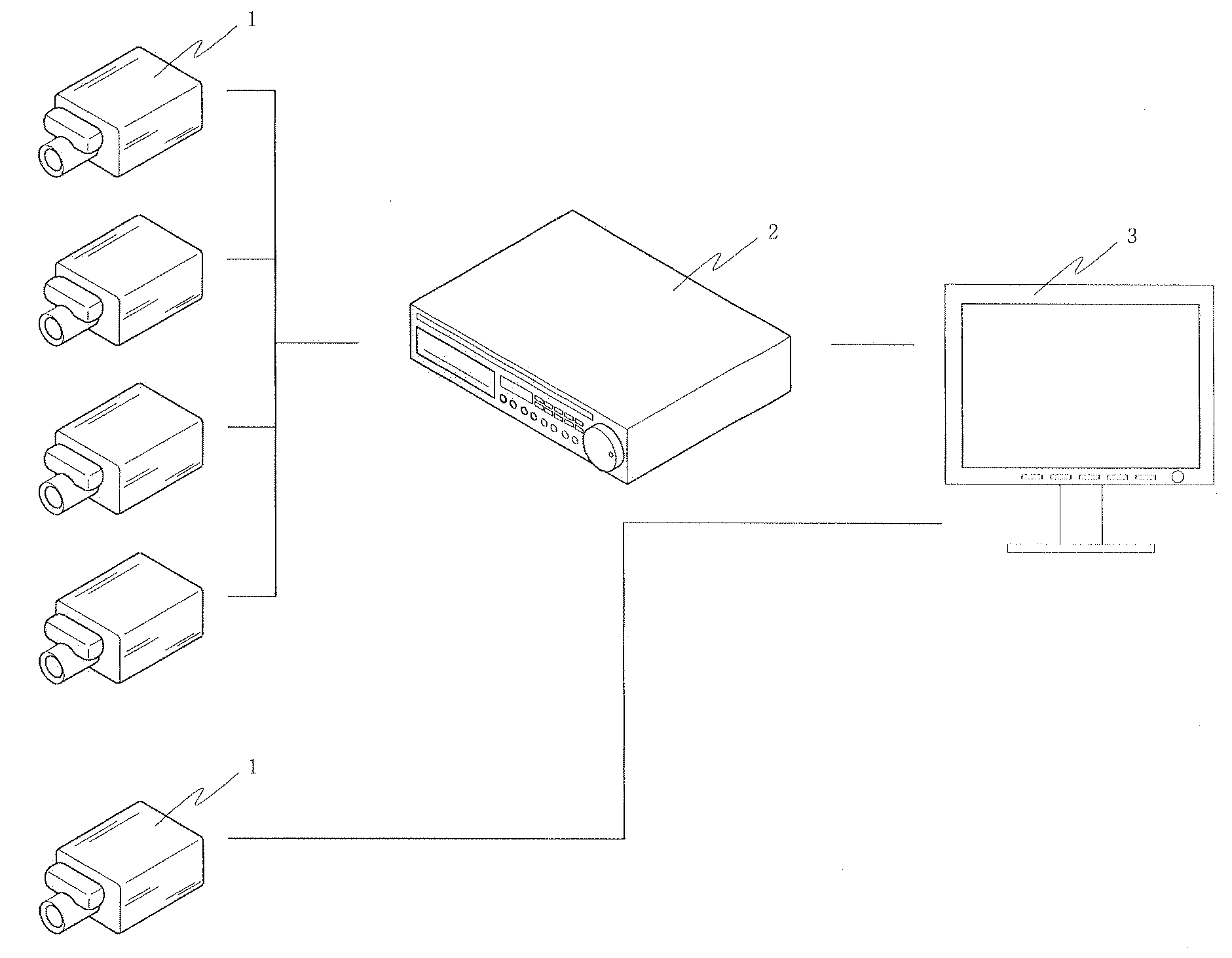
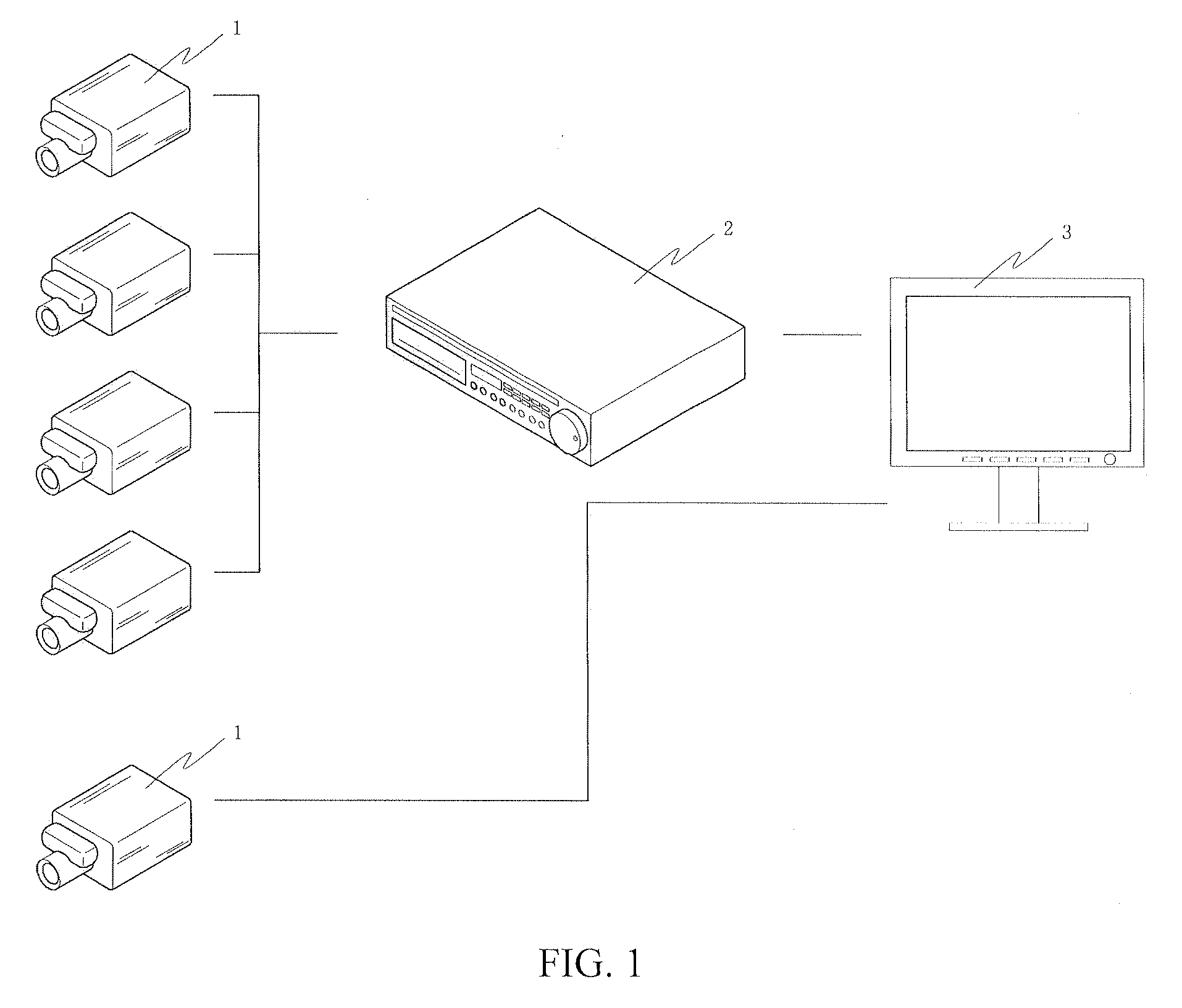
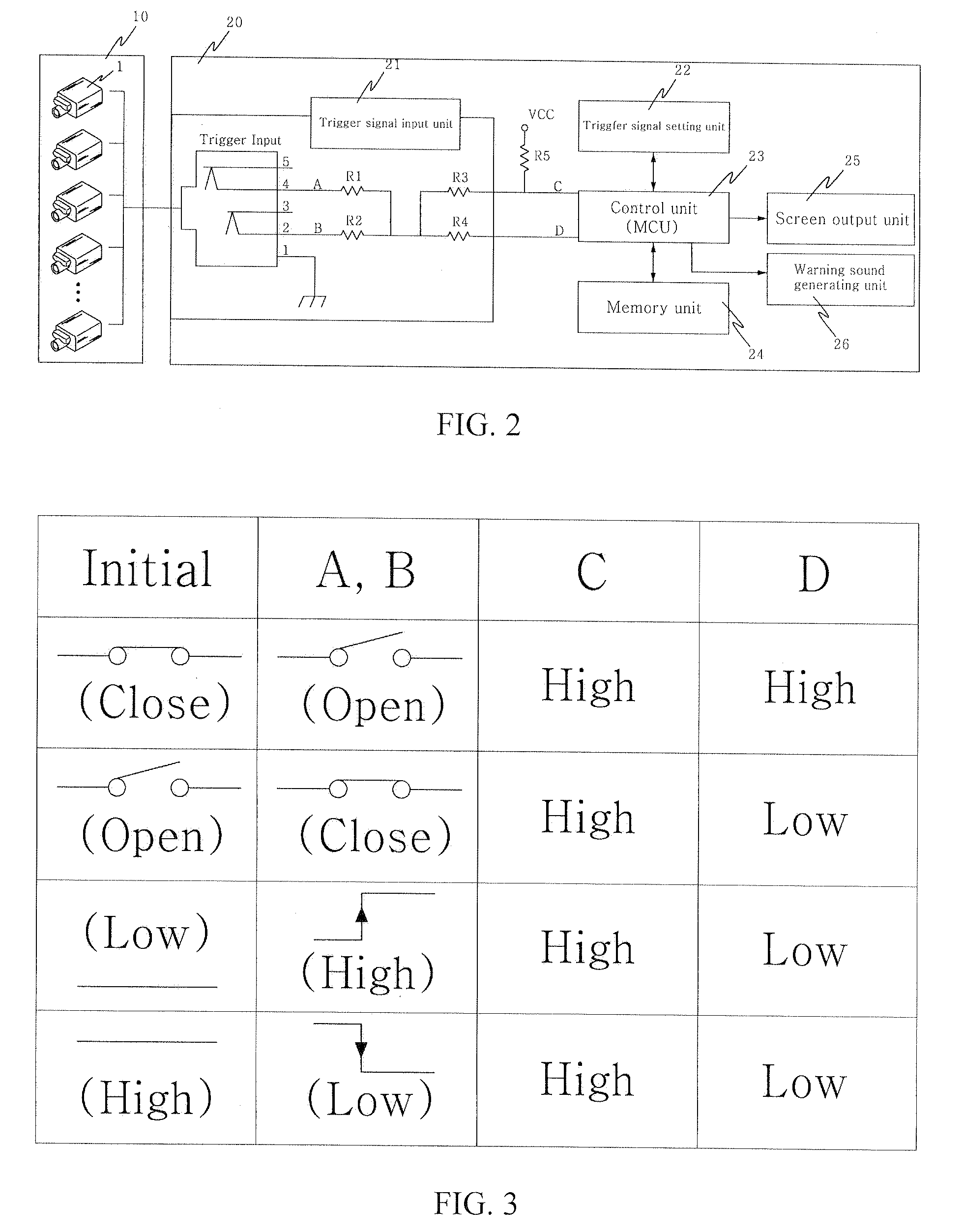
[0023]FIG. 1 is a configuration view showing a conventional monitor observation system. FIG. 2 is an overall configuration view showing a monitor observation system which is applied to the present invention. FIG. 3 is an illustration showing trigger signal options of the monitor observation system which is applied to the present invention. FIG. 4 is a flow chart showing an observation control process of the monitor observation system which is applied to the present invention. FIG. 5 is an illustration showing a trigger signal setting unit of the monitor observation system which is applied to the present invention. Reference numeral 1 is a surveillance camera, reference numeral 2 is an image reproduction apparatus, and reference numeral 3 is a monitor.

[0024]As shown therein, a monitor de...


PUM


Abstract

The present invention implements a monitor observation system, comprising: an external device installed in an observation object area to output a trigger signal in accordance with an input signal source; and a monitor device for detecting the trigger signal outputted from the external device, checking whether the trigger signal conforms to a preset trigger signal condition or not, if so, outputting a corresponding warning sound, and performing transition to the screen conforming to the preset trigger signal condition for displaying.

Description

BACKGROUND OF THE INVENTION[0001]1. Field of the Invention[0002]The present invention relates to a monitor observation system and its observation control method, and more particularly, to a monitor observation system, which allows a user to quickly check if something is wrong with an observation object area and conduct intensive management by identifying a trigger signal outputted from various external devices installed in an observation object area, outputting a corresponding warning sound upon occurrence of an event, and performing screen transition for the corresponding area on a monitor device, and its observation control method.[0003]2. Discussion of the Related Art[0004]Generally, an observation system using a monitor is a series of devices that are adapted to observe if something is wrong with the inside of an observation zone by using a typical surveillance camera. In such a monitor observation system, a surveillance camera is installed in a place where it can watch, a video...

Claims


Application Information

Patent Timeline
Patent Type & Authority Applications(United States)
IPC IPC(8): H04N7/18
CPCG08B13/19634G08B13/19691H04N7/188H04N7/18
Inventor KIM, WOL SUP
Owner ORION TECH
Learn More