Display system including first and second display devices

a display device and display device technology, applied in the field of display systems, can solve the problems of inconvenient users, portable communication terminals that cannot display the screen as desired by users, image forming apparatus cannot handle flick operation, etc., and achieve the effect of improving user convenien

Active Publication Date: 2015-06-30
KONICA MINOLTA BUSINESS TECH INC
View PDF19 Cites 0 Cited by
  • Summary
  • Abstract
  • Description
  • Claims
  • Application Information

AI Technical Summary

Benefits of technology

[0012]An object of the present invention is to provide a display device capable of improving the user's convenience.

Problems solved by technology

However, with the conventional technique, when flick operation is performed at a portable communication terminal, an image forming apparatus cannot handle the flick operation, and the portable communication terminal thus cannot display a screen as desired by the user.
This is inconvenient for users.
This is not only the problem between an image forming apparatus and a portable communication terminal and is a common problem to a display system including a first display device for storing screen data and a second display device for displaying a screen based on the screen data stored by the first display device.

Method used


Image

  • Display system including first and second display devices
  • Display system including first and second display devices
  • Display system including first and second display devices

Examples


first embodiment

[0046]First of all, a configuration of a display system in the present embodiment will be described.

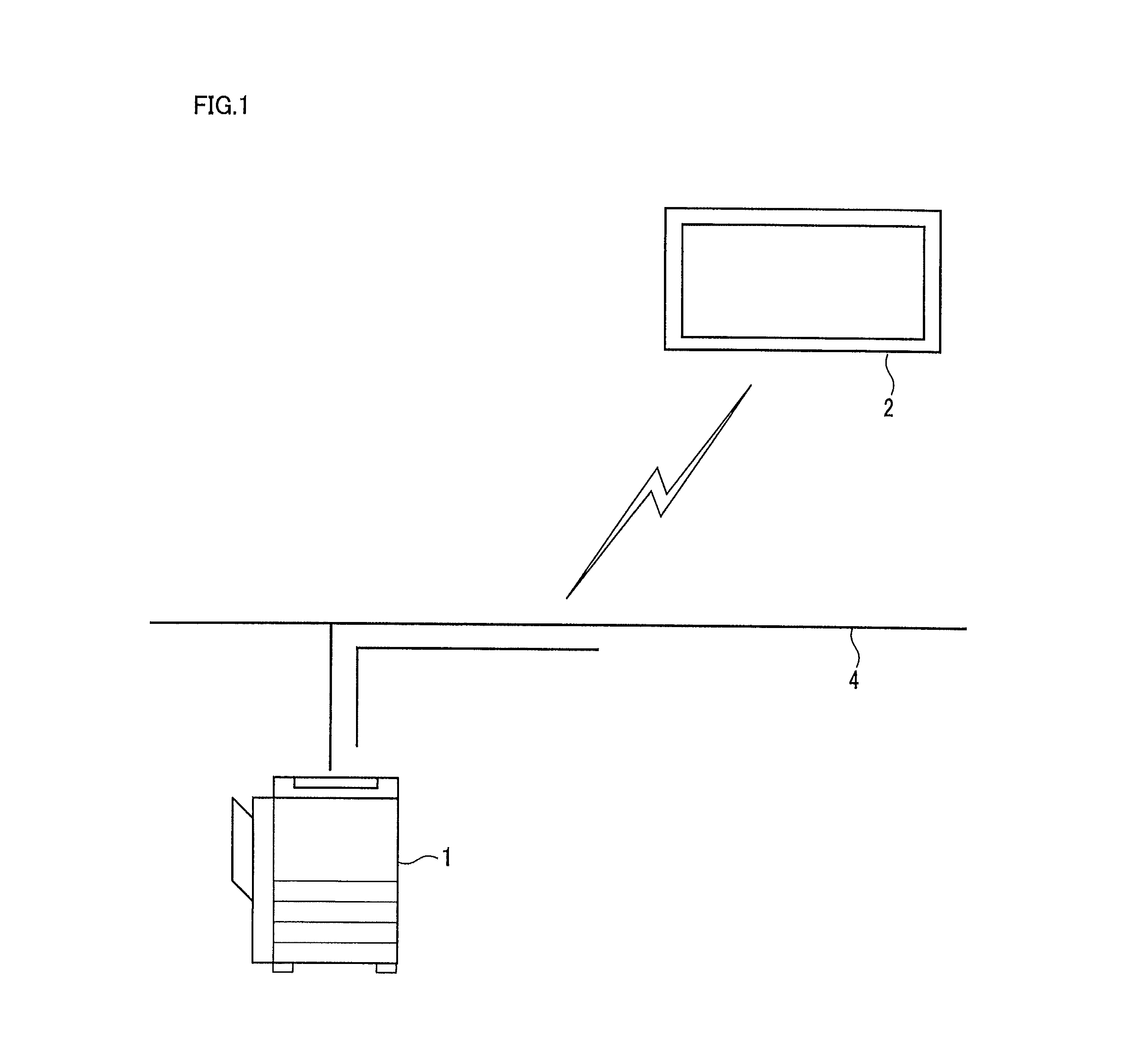
[0047]Referring to FIG. 1, a display system includes an image forming apparatus 1 and a portable communication terminal 2. The image forming apparatus 1 is, for example, an MFP (Multi-Functional Peripheral) having a scanner function, a facsimile function, a copy function, a printer function, a data communication function, and a server function. Image forming apparatus 1 is connected with an external device (not shown) and portable communication terminal 2 via a network 4.

[0048]Network 4 is, for example, a wired or wireless LAN (Local Area Network) or any other network using a dedicated line. Network 4 connects various kinds of devices using a protocol such as TCP / IP (Transmission Control Protocol / Internet Protocol). The devices connected to network 4 can exchange data with each other. Network 4 may be a network using a public line or using radio communication.

[0049]Image forming appar...

second embodiment

[0078]In the present embodiment, panel A creates screen data having a resolution lower than the resolution of screen data stored by panel A, as screen data from the start of movement to before completion of movement, and transmits the created screen data to panel B.

[0079]FIG. 8 is a sequence diagram showing an example of communication between panel A and panel B in a second embodiment of the present invention.

[0080]Referring to FIG. 8, upon detection of flick operation on panel B, panel. B gives a notice of flick information to panel B. Panel A calculates a position where movement of the screen is completed (the final position in screen movement) based on the received flick information. Next, panel A creates screen data of screens (the screen data with a reduced resolution) from the start of movement to completion of movement with a resolution lower than the resolution (the resolution of the screen data displayed on panel A) of the screen data stored in fixed memory 110 of panel A, ...

third embodiment

[0093]In the present embodiment, panel A transmits screen data having the same resolution as the resolution of screen data stored by panel A, to panel B, as screen data of the screen on completion of movement.

[0094]FIG. 11 is a sequence diagram showing an example of communication between panel A and panel B in a third embodiment of the present invention.

[0095]Referring to FIG. 11, panel A creates screen data having the same resolution (hereinafter this resolution may be referred to as a normal resolution) as the resolution of the screen data stored in fixed memory 110 of panel A (the resolution of the screen data displayed on panel A), as screen data of the last screen (screen data of the screen on completion of movement) and transmits the created screen data to panel B.

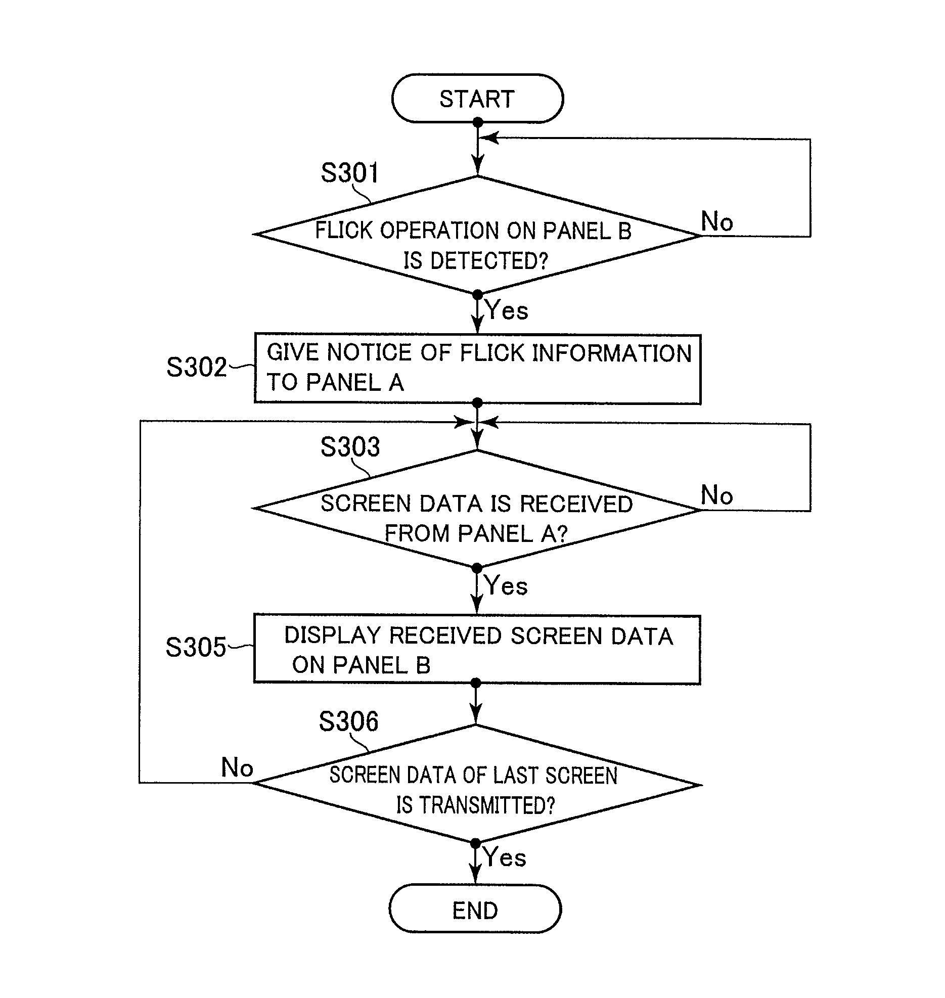
[0096]FIG. 12 is a flowchart illustrating operation of panel A in a case where flick operation is accepted on panel B in the third embodiment of the present invention.

[0097]Referring to FIG. 12, in this flowchart, fi...


PUM


Abstract

A display system includes an image forming apparatus for storing screen data and a portable information terminal for displaying a screen based on the screen data stored by the image forming apparatus. The display system accepts flick operation for requesting movement of a screen at the portable communication terminal and transmits flick information concerning the flick operation to the image forming apparatus. The display system successively transmits screen data of screens from the start of movement to completion of movement from the image forming apparatus to the portable communication terminal, based on the flick information. The display system displays a screen based on the transmitted screen data on the portable communication terminal.

Description

[0001]This application is based on Japanese Patent Application No. 2011-231116 filed with the Japan Patent Office on Oct. 20, 2011, the entire content of which is hereby incorporated by reference.BACKGROUND OF THE INVENTION[0002]1. Field of the Invention[0003]The present invention relates to a display system and more particularly to a display system including a first display device for storing screen data and a second display device for displaying a screen based on the screen data stored by the first display device.[0004]2. Description of the Related Art[0005]In recent years, portable communication terminals have been more and more sophisticated, and people own portable communication terminals in place of PCs (Personal Computers). Portable communication terminals allow documents in electronic form to be viewed and edited at any place. Portable communication terminals are used in various business and daily life situations.[0006]With sophistication of portable communication terminals,...

Claims


Application Information

Patent Timeline
Patent Type & Authority Patents(United States)
IPC IPC(8): G09G5/00H04B7/005G09G5/10H04N7/14G06F3/0488G06F3/14G09G5/34
CPCG06F3/04883G06F3/1454G09G5/34G09G2340/02G09G2340/0407G09G2350/00G09G2370/022
Inventor AMIYA, KOICHIKUNO, TAKATSUGUIWAMOTO, HIROSHIMURAKAMI, HIROSHITANAKA, YUSAKUSAWADA, KENICHI
Owner KONICA MINOLTA BUSINESS TECH INC
Why Eureka
Try Eureka