
Eureka
For R&D, Eureka makes reading and utilizing patents & technical documents easy.
Eureka AIR
Designed for self-driven R&D workflows. Generate viable solutions, solve complex R&D challenges, empower your innovation with AI.

Eureka Materials
Designed for material experts only. Revolutionize your material R&D, from search, analyze, to developing new materials.

TechResearch
Generate reliable direction feasibility study reports for your R&D in just a few steps.

TechSeek
Discover and master advanced knowledge NOW. Basics, ideas, possibilities, all at once.

TechMind
As an expert in R&D Theories, TechMind can generates customized viable solutions instantly.

TechRisk
Analyze your overall solution with one click, know your potential R&D risks in advance.

TechMonitor
Get weekly tech updates, stay abreast of the latest tech innovations and key insights.
Butt joint for trailer side wall
- Summary
- Abstract
- Description
- Claims
- Application Information
AI Technical Summary
Benefits of technology
Problems solved by technology
Method used
Image

Examples
first embodiment
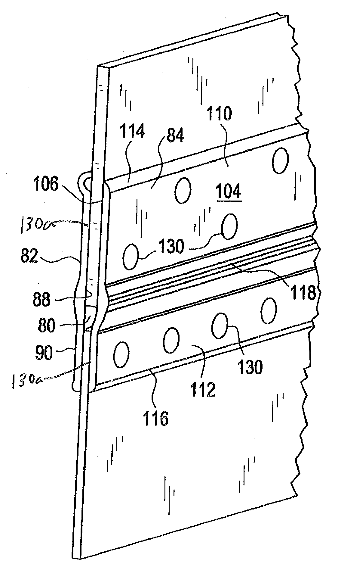
[0042]FIGS. 2-8 illustrate the butt joint 50 of the The butt joint 50 includes an outer member 82 and an inner member 84 spaced from the outer member 82. A channel 86 is provided between the outer and inner members 82, 84 for receiving the side panels 46 and the base rail 44.
[0043]As best shown in FIG. 6, the outer member 82 generally includes an inner surface 88, an outer surface 90, a front end (not shown), a rear end 92, an upper portion 94, a lower portion 96, an upper end 98, a lower end 100, and a rub rail 102. The inner surface 88 is generally planar. Each of the upper end 98, lower end 100, and the rub rail 102 is elongated, extends from the front end to the rear end 92, and are generally parallel to each other. The rub rail 102 is spaced from the upper and lower ends 98, 100 and extends outwardly. The rub rail 102 has a generally arc-shaped cross-section extending from the outer surface 90 such that the rub rail 102 provides a thickened portion of the outer member 82. The ...
second embodiment
[0053]FIG. 9 shows the butt joint 200. The butt joint 200 includes an outer member 202 and an inner member 204 which are similar to the outer and inner members 82, 84 of the butt joint 50, with the following exceptions.
[0054]The outer member 202 includes an inwardly extending tongue 206. The tongue 206 extends opposite the rub rail 102 and is generally perpendicular to the inner surface 88 of the outer member 202. The tongue 206 extends from the front end to the rear end 92 of the outer member 202. Unlike the lower end 100 of the outer member 82 which provides a generally semi-circularly shaped cross-section, the lower end 215 of the outer member 202 provides an arc-shaped cross-section.
[0055]The inner member 204 includes an upper flange 208 and a lower flange 210, each extending outwardly opposite the rub rail 118. The upper and lower flanges 208, 210 extend from the front end to the rear end of the inner member 204. The upper and lower flanges 208, 210 generally extend perpendicul...
third embodiment
[0061]FIG. 10 illustrates the butt joint 300 of the The butt joint 300 is identical to the butt joint 50 shown in FIG. 9 except for the following. Rather than a single inwardly extending tongue, the outer member 302 of the butt joint 300 includes upper and lower inwardly extending flanges 304, 306. Rather than two outwardly extending flanges, the inner member 308 includes a single outwardly extending tongue 310. When assembled, the tongue 310 of the inner member 308 extends within the gap provided between the upper and lower flanges 304, 306 of the outer member 302. The interengaged tongue 310 and flanges 304, 306 provide a bridge between the outer member 302 and the inner member 308.
[0062]As shown, the upper and lower portions 122, 124 of the channel 86 have the same width. The portions 122, 124 of the channel 86 can of course be modified to accept panels 46 and base rails 44 having varying widths.
PUM
| Property | Measurement | Unit |
|---|---|---|
| Width | aaaaa | aaaaa |
Abstract
Description
Claims
Application Information
 - R&D Engineer
- R&D Manager
- IP Professional
- Industry Leading Data Capabilities
- Powerful AI technology
- Patent DNA Extraction
Browse by: Latest US Patents, China's latest patents, Technical Efficacy Thesaurus, Application Domain, Technology Topic, Popular Technical Reports.
© 2024 PatSnap. All rights reserved.Legal|Privacy policy|Modern Slavery Act Transparency Statement|Sitemap|About US| Contact US: help@patsnap.com