

Restraint system for walkie/rider pallet truck
a walkie/rider and pallet truck technology, applied in the directions of transportation and packaging, pedestrian/occupant safety arrangements, vehicular safety arrangements, etc., can solve the problems of time-consuming, disadvantageous lifting operation, and extra walking steps
- Summary
- Abstract
- Description
- Claims
- Application Information
AI Technical Summary
Benefits of technology
Problems solved by technology
Method used
Image

Examples
second embodiment
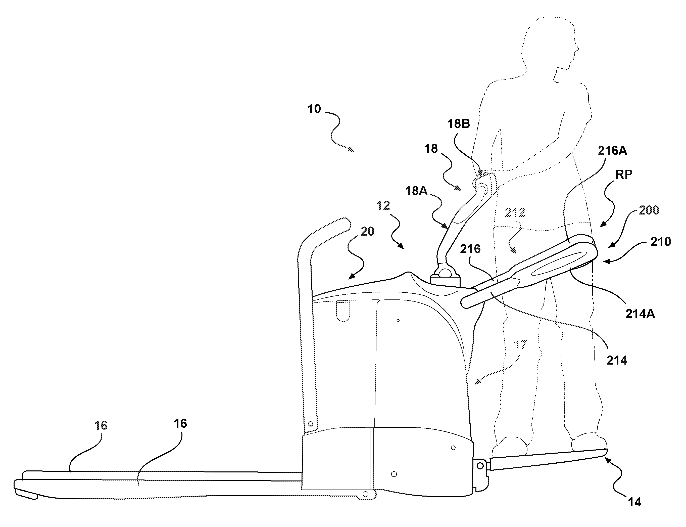
[0068]A restraint structure 310 constructed in accordance with the present invention is illustrated in FIG. 18. The restraint structure 310, when located in a quick-exit position QP, is positioned upward and slightly away from vertical V, i.e., on a side of vertical V near the operator and towards the platform 14, and at an angle θ310 to vertical V, wherein the angle θ310 may have a magnitude falling within a range of from about 0 degrees to about 25 degrees, see FIG. 18. The restraint structure 310 comprises a U-shaped tubular structure 312 having first and second leg members (only the first leg member 314 is illustrated in FIG. 18) and an intermediate member 315. A holding mechanism 317 comprising, in the illustrated embodiment, a spring clip 317A fixed to the truck power unit and a holding member 317B fixed to the intermediate member 315, is provided for holding the restraint structure 310 in the quick-exit position on the side of vertical V near the operator and towards the plat...
third embodiment
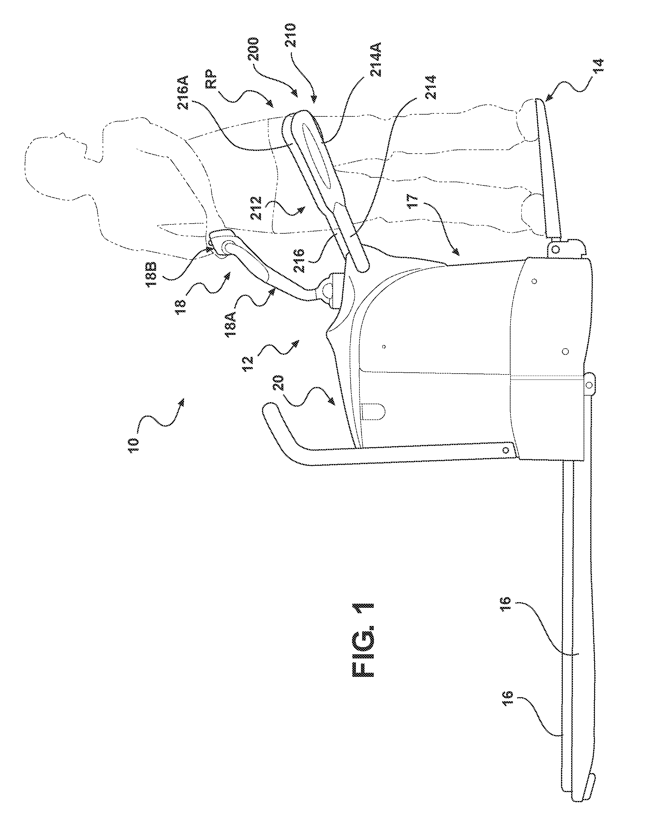
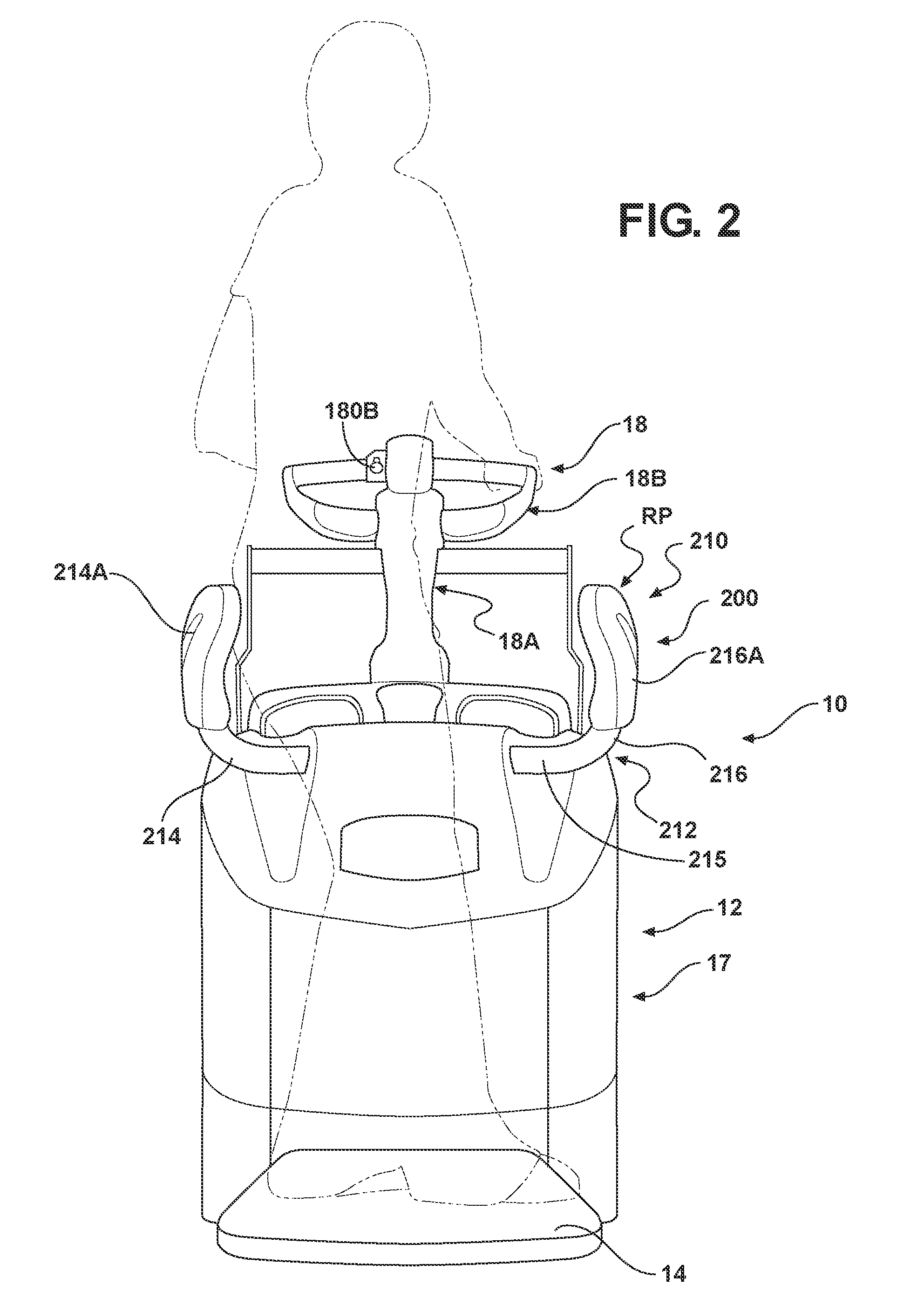
[0069]A restraint system 400 constructed in accordance with the present invention is illustrated in FIGS. 19 and 20 and comprises a restraint structure 410 coupled to a power unit main housing 17. In the illustrated embodiment, the restraint structure 410 comprises a U-shaped tubular structure 412 having first and second L-shaped leg members 414 and 416 provided with first and second pads 414A and 416A. An end portion 1414 of the first L-shaped leg member 414 is capable of being received within a bore (not shown) defined within an end portion 1416 of the second L-shaped leg member 416 such that the first L-shaped leg member 414 is capable of moving / rotating relative to the second L-shaped leg member 416 and vice versa. A polymeric bushing (not shown) may be provided within the bore in the second L-shaped leg member 416 so as to allow the end portion 1414 of the first L-shaped leg member 414 to move easily relative to the end portion 1416 of the second L-shaped leg member 1416. Each ...
fourth embodiment
[0089]A restraint system 700 constructed in accordance with the present invention is illustrated in FIG. 21 and comprises a restraint structure 710 comprising inwardly foldable first and second leg members 714 and 716, each of which is separately coupled to a truck power unit P. The first and second leg members 714 and 716 are each positionable in a first stowed position against the power unit P and a second, outwardly extending rider-driving position, as shown in FIG. 21, so as to extend along opposing sides of an operator when the operator is standing on a truck platform. As illustrated in FIG. 21, the first leg member 714 is pivotable about a substantially vertical axis V714 so as to allow the first member 714 to move between its stowed and rider-driving positions. The second leg member 716 is likewise pivotable about a substantially vertical axis so as to allow the second leg member 716 to move between its stowed and rider driving positions. The first leg member 714 is further p...
PUM
 Abstract
Description
Claims
Application Information