Indicator

Active Publication Date: 2010-04-15
NAGANO KEIKI
View PDF1 Cites 3 Cited by
  • Summary
  • Abstract
  • Description
  • Claims
  • Application Information

AI Technical Summary

Benefits of technology

[0029]With the above arrangement, since the monitor indicator is provided on a s

Problems solved by technology

However, since such an indicator forces an operator to digitally read whether the measured value is within the dangerous range or not and since the display is provided only on the front side of the indicator, the operator at the lateral or back o

Method used


Image

  • Indicator
  • Indicator
  • Indicator

Examples


Embodiment Construction

)

[0041]A first exemplary embodiment of the invention will be described below with reference to the attached drawings.

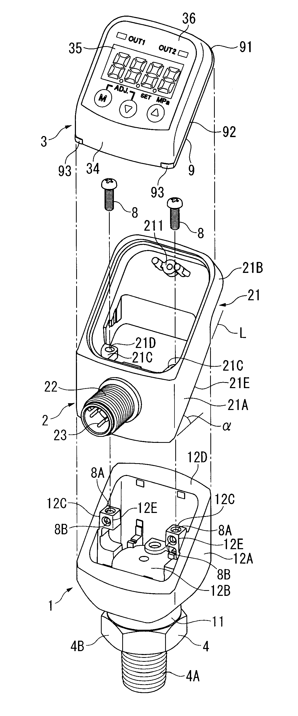
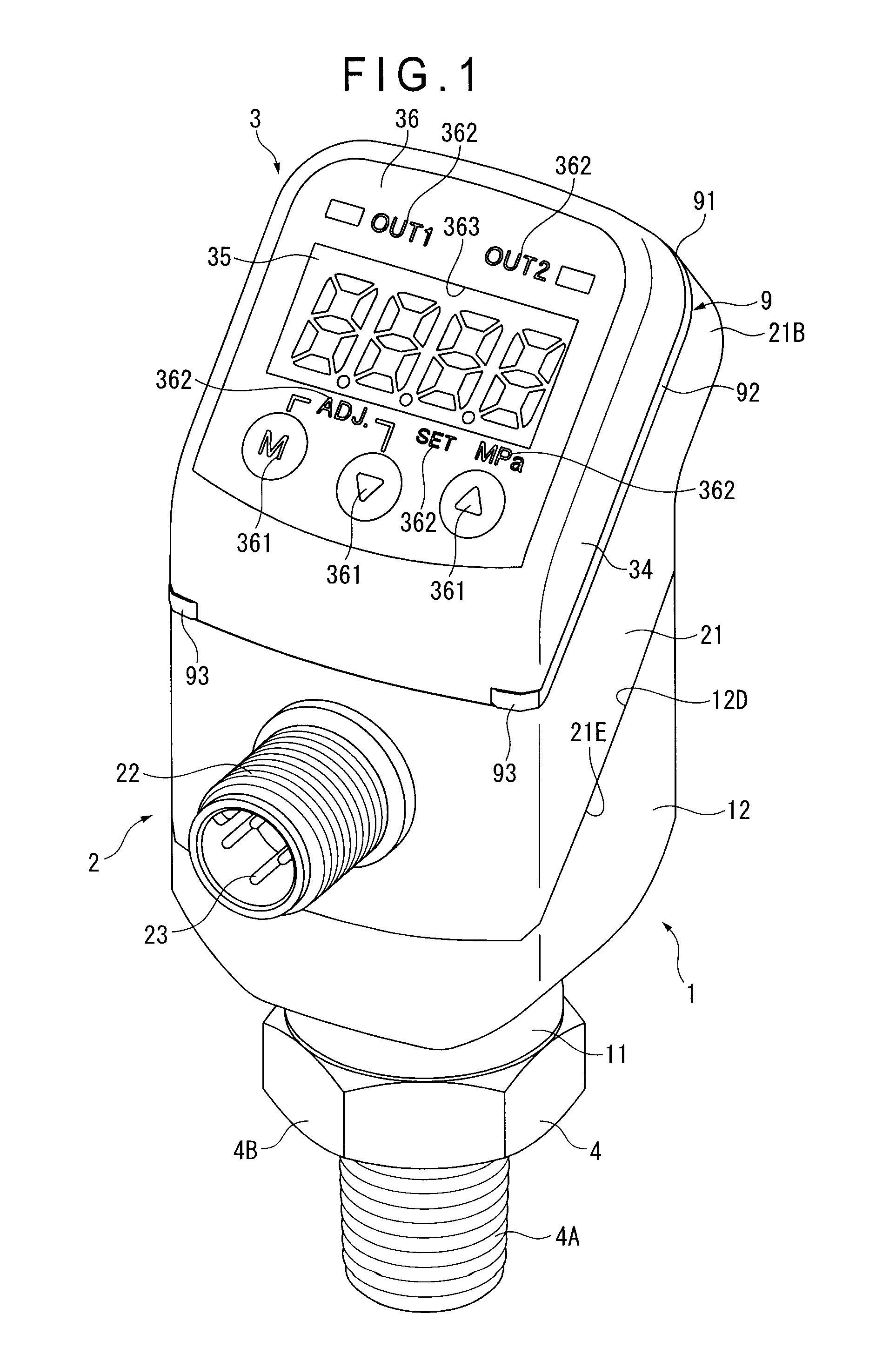
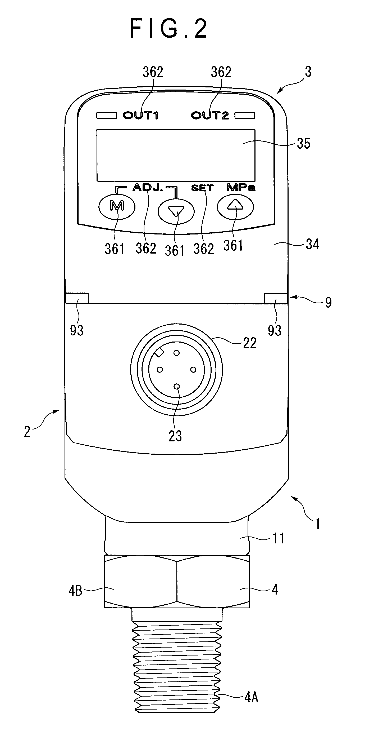
[0042]FIG. 1 is a perspective view showing an entire arrangement of an indicator according to the first exemplary embodiment. FIG. 2 is a front elevational view of the indicator. FIG. 3 is a perspective view showing an obliquely back side of the indicator. FIG. 4 is a cross section of the indicator. FIG. 5 is an exploded perspective view of the indicator.

[0043]As shown in FIGS. 1 to 5, the indicator is a gauge pressure measurement indicator, including: a holder 1; a case 2 jointed on the holder 1; a display 3 provided on an upper opening end (first end) of the case 2; and a monitor indicator 9 provided between the display 3 and the case 2 for checking an operation of the indicator.

[0044]A joint 4 (connector) is attached to a lower end (first end) of the holder 1.

[0045]The joint 4 has: a pipe-side screw 4A screwed to a pipe P (attached portion); a flange 4B connected w...


PUM


Abstract

A numeral-displaying face provided with a numeral-display and an exterior wall intersecting a periphery of the numeral-displaying face are provided on a cover and a case body of an indicator. A monitor indicator for checking an operating condition of the indicator is provided on the exterior wall. An outer circumference of the monitor indicator is flush with the exterior wall. A fallen object does not collide with the monitor indicator, so that damage on the monitor indicator can be prevented.

Description

[0001]The entire disclosure of Japanese Patent Application No. 2008-266912, filed Oct. 15. 2008, is expressly incorporated by reference herein.BACKGROUND OF THE INVENTION[0002]1. Field of the Invention[0003]The present invention relates to an indicator provided with a numeral-displaying face having a numeral-display and an exterior wall.[0004]2. Description of Related Art[0005]An indicator such as a pressure indicator is provided with a numeral-display for numerically displaying a measured value. The numeral-display digitally displays a detected measured value. Based on the digitally displayed value, whether the measured value is within a tolerable range or not (i.e. in a dangerous range) is read.[0006]The numeral-display is typically provided on a front side of an indicator. Accordingly, the measured value can only be seen from the front side, where the measured value cannot be read from lateral and back sides. However, since such an indicator forces an operator to digitally read w...

Claims


Application Information

Patent Timeline
IPC IPC(8): G08B5/22G09F9/33G08B21/00
CPCG01D11/24G01D7/00
Inventor SATO, YUZURUITE, TAKAYUKIKOBAYASHI, TOSHIAKI
Owner NAGANO KEIKI
Why Eureka
Try Eureka