Display apparatus

Active Publication Date: 2010-03-02
YAZAKI CORP
View PDF8 Cites 0 Cited by
  • Summary
  • Abstract
  • Description
  • Claims
  • Application Information

AI Technical Summary

Benefits of technology

[0029]According to the invention claimed in claim 4, since the tip end portion of the indicator can be dis

Problems solved by technology

To this end, since such a space shown by A is required, there arises a problem that the size of the display apparatus becomes large.
Further, sinc

Method used


Image

  • Display apparatus
  • Display apparatus
  • Display apparatus

Examples


Example

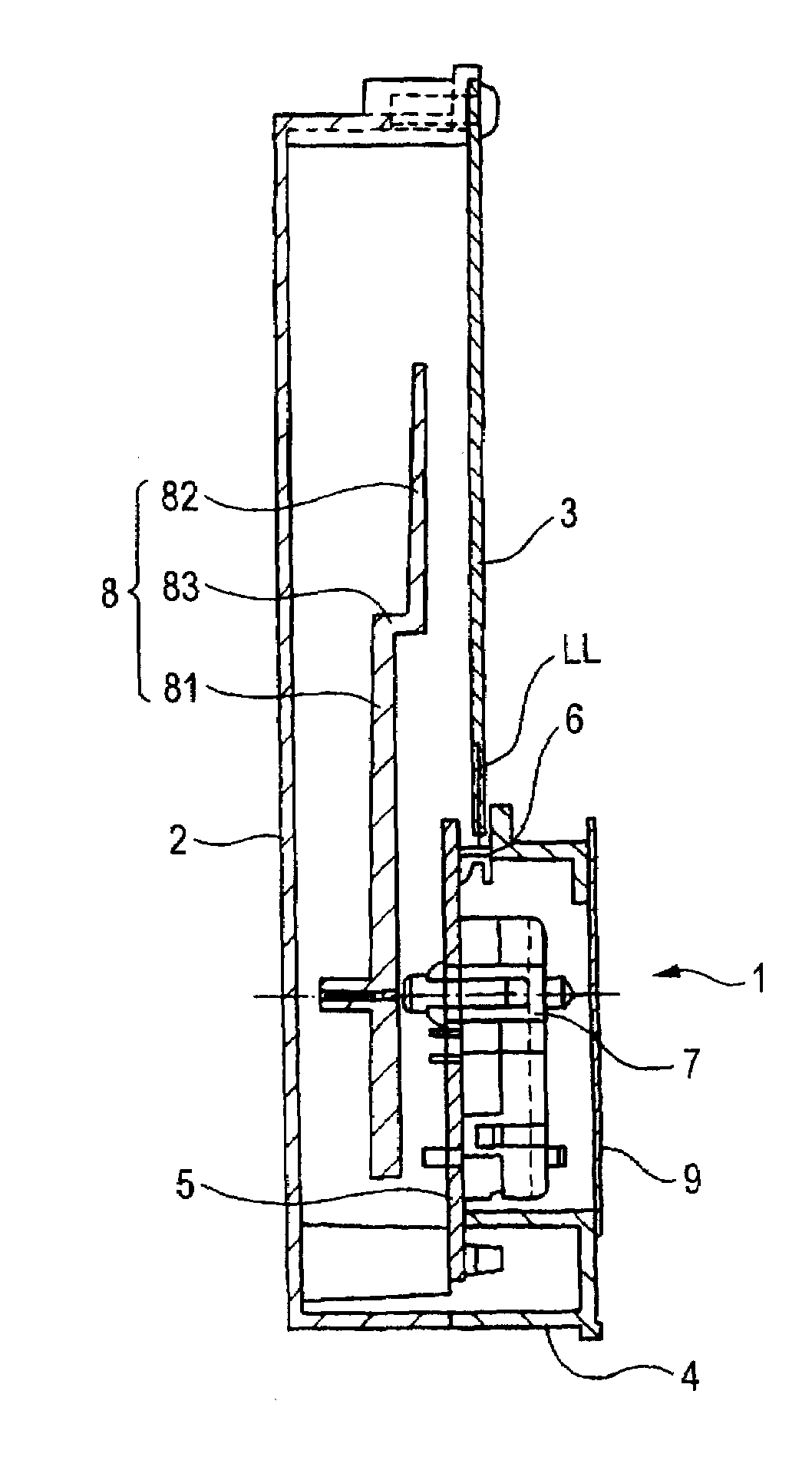
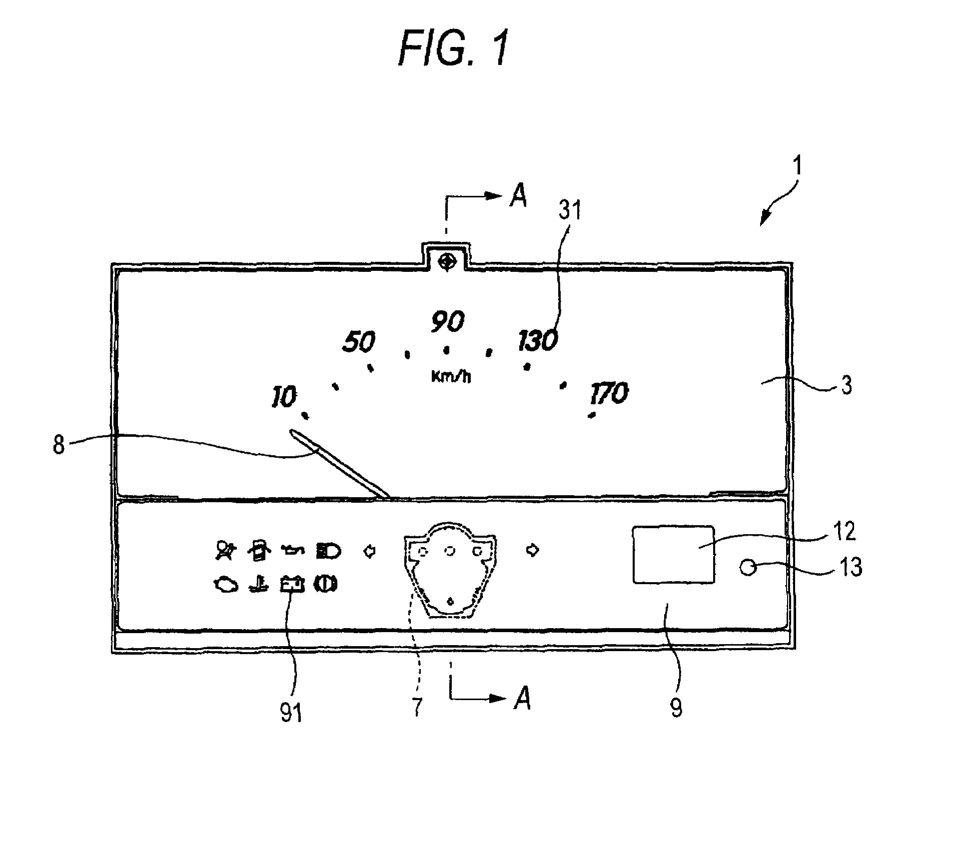
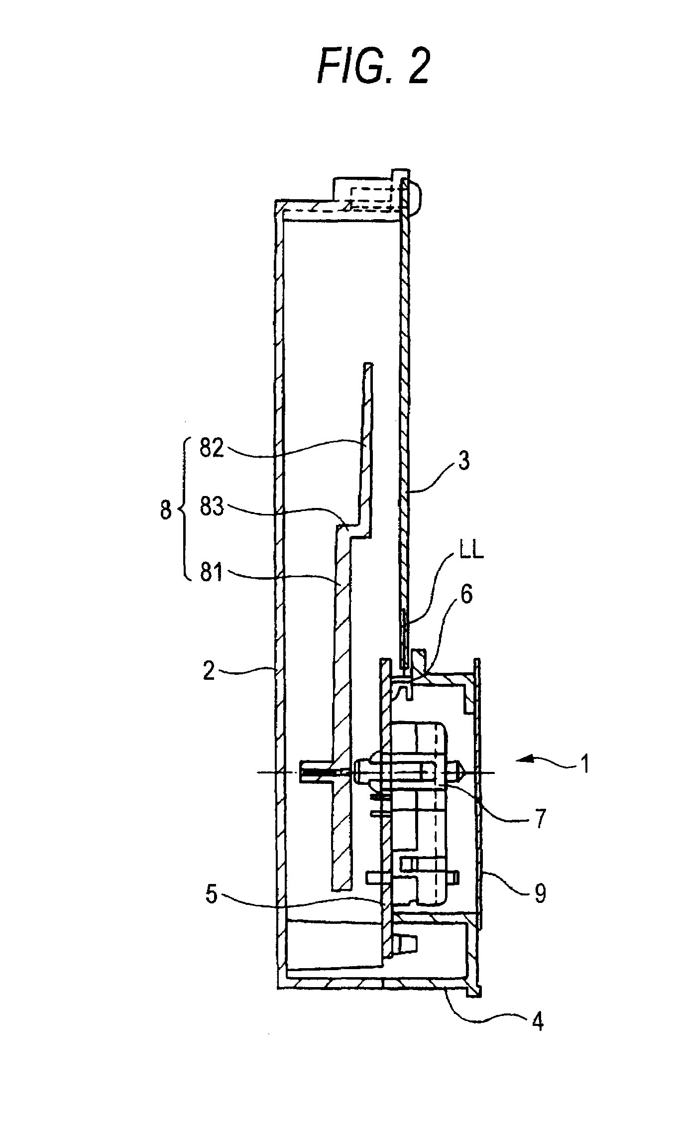
[0034]Hereinafter, an embodiment according to the invention will be explained below. The display apparatus according to the embodiment of the invention is used for a speed meter shown in FIG. 1.

[0035]The display apparatus 1 is an apparatus that is mounted on a movable body such as an automobile and displays a status of the movable body with respect to an occupant of the movable body. As shown in the figure, the display apparatus 1 includes a rear cover 2, a transparent display panel 3, a case 4, a printed board 5 serving as a board, LEDs 6 for the transparent display panel serving as light sources, a movement 7, an indicator 8 and a display panel 9.

[0036]The rear cover 2 is formed in a saucer shape which is opened on the case 4 side. The rear cover 2 is provided with bosses 21 etc. for screwing the panel 3, the case 4 and the printed board 5 described later by screws 10. As shown in FIG. 2, the panel 3 is disposed above the rear cover 2. The panel 3 is configured almost in a rectang...


PUM


Abstract

To provide a display apparatus which is intended to improve the miniaturization and illumination efficiency, an indicator 8 is disposed on the rear surface side of a transparent display panel 3. A printed board 5 mounts a movement 7 on the front surface thereof so as not to overlap the movement 7 and the transparent display panel 3 and mounts the indicator 8 on the rear surface thereof. LEDs 6 for the transparent display panel are mounted on the front surface of the printed board 5 so as to oppose to the outer peripheral surface of the transparent display panel 3.

Description

BACKGROUND OF THE INVENTION[0001]1. Field of the Invention[0002]The present invention relates to a display apparatus and, in particular, relates to a display apparatus including a transparent display panel on which indexes are formed and an indicator which is disposed on the rear surface side of the transparent display panel and indicates the indexes.[0003]2. Description of the Related Art[0004]A display apparatus shown in FIG. 4, for example, is proposed as the aforesaid display apparatus (a patent document 1). As shown in the figure, a display apparatus 100 includes a transparent display panel 3, an indicator 8, a printed board 5, a movement 7 and an LED 6 for the transparent display panel serving as a light source.[0005]The transparent display panel 3 is configured by a light guide member formed by translucent resin. The transparent display panel includes a display panel main body 32, which is arranged in a manner that indexes such as characters and graduations 31 are printed by ...

Claims


Application Information

Patent Timeline
IPC IPC(8): G01D11/28G01D13/22
CPCB60K35/00G01D11/28G01D13/28G09F13/02B60K37/02Y10S116/36
Inventor KIMURA, HIROMICHITAKAO, KOUICHI
Owner YAZAKI CORP
Why Eureka
Try Eureka