Magnifying lens cover for combination padlocks

Active Publication Date: 2007-06-21
SUN LOCK COMPANY LIMITED -THE-
View PDF15 Cites 0 Cited by
  • Summary
  • Abstract
  • Description
  • Claims
  • Application Information

AI Technical Summary

Benefits of technology

[0017] In the preferred construction of the present invention, a single housing and shackle assembly are employed and constructed for enabling the shackle to be released from locked engagement with the housing using either a rotatable dial combination construction or a key-activated tumbler construction. In this way, a dual locking and releasing padlock is achieved which satisfies all of the new requirements for padlocks being used for travel wherein customs officers and/or security personnel are required to inspect the suitcase or other container.
[0018] In the preferred construction or the present invention, a generally conventional J-shaped shackle is employed with one portion of the housing cooperatively associated with the longer leg of the shackle. In addition, this portion of the housing is also constructed with rotatable, combination defining dials which control the axial movement of the longer leg of the shackle. In this way, the axial movement of the shackle in the housing is completely controlled by the rotatable, combination defining dials, enabling the locking and releasing of the shackle relative to the housing to be easily achieved by employing the known combination.
[0019] In addition, in accordance with the teaching of the present invention, a magnifying member is securely affixed to the housing in cooperating association with the rotating dials thereof. By positioning the magnifying member in overlying, aligned relationship with the rotatable dials, the visibility of the indicia formed on each dial is greatly enhanced. As a result, any user is able to immediately determine and recognize the different indicia formed on each rotatable dial, and quickly position the combination of indicia which represent the preselected combination for releasing the shackle from locked engagement with the housing.
[0020] Although the magnifying member of the present invention can be constructed in a wide variety of alternate configurations, without departing from the scope of the present invention, it has been found that a simple, easily constructed and easily secured magnifying member is able to achieve a

Problems solved by technology

Although locks of this general nature have been available for several decades, these prior art combination lock constructions suffer from common deficiencies which have not been successfully overcome.
Although many manufacturers have attempted to solve the problems associated with rotatable dial or combination locks, one principal difficulty and drawback these prior art constructions have been unable to overcome is a construction which provides an easily seen visual display to the user when the desired combination is being entered.
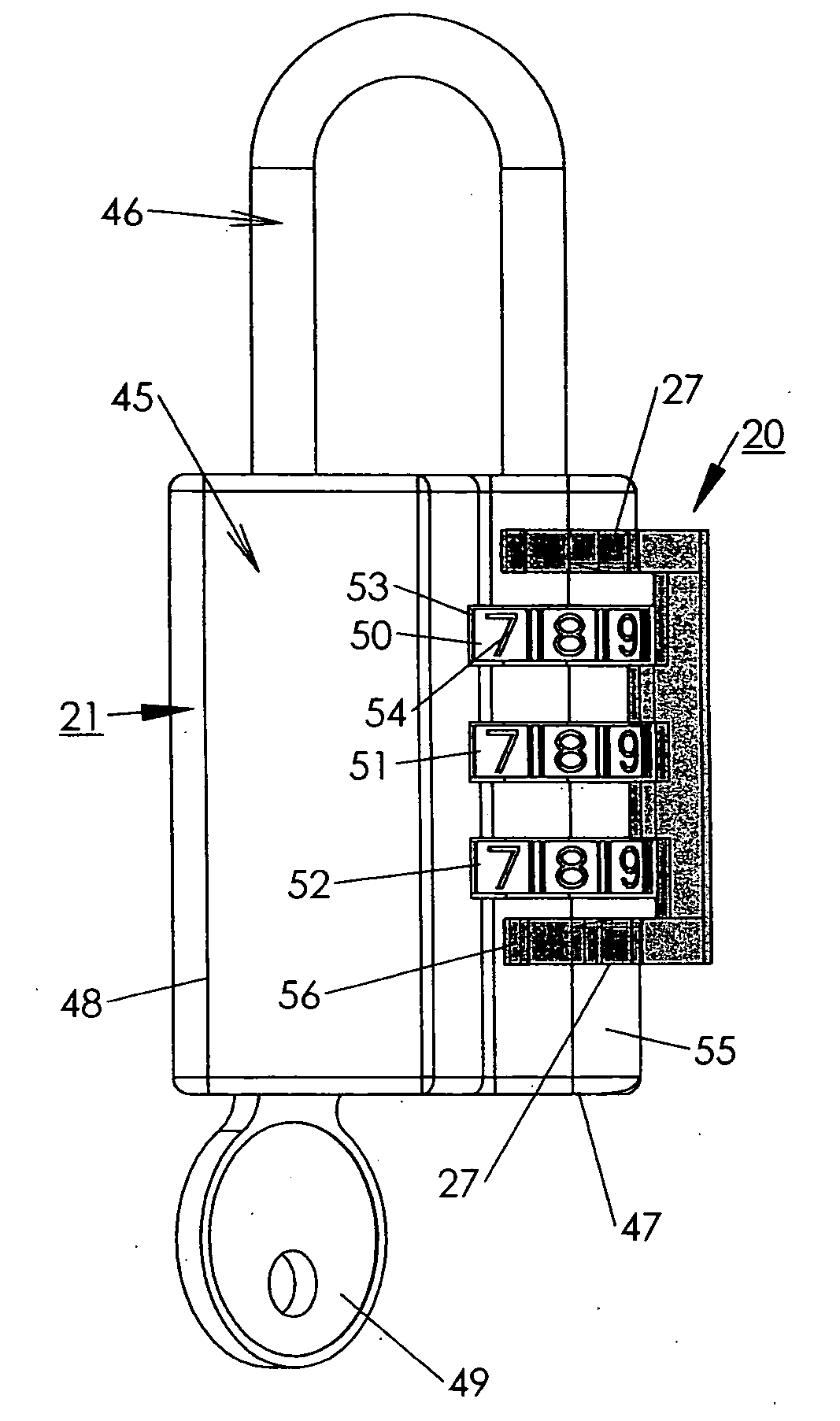
In such instances when the known combination is not easily seen and properly entered, the entire combination lock is incapable of being opened, since the user is unable to release the shackle from locked engagement with the housing.
In addition, although key operated locks do not suffer from the difficulty of having the combination changed or altered without the user's knowledge, users are frequently incapable of using key operated locks, due to the key being lost or misplaced.
As a result, prior art key operated locks are also frequently discarded due to the user's inability to find a particular key for operating the lock.
Another common problem which has consistently plagued prior art constructions is the cost of construction for producing and assembling prior art padlocks, whether the padlock is key operated or combination operated.
In order to attain a padlock which provides all of the features desired by consumers, prior art constructions typically incorporate numerous small components, each of which require expensive assembly proce

Method used


Image

  • Magnifying lens cover for combination padlocks
  • Magnifying lens cover for combination padlocks
  • Magnifying lens cover for combination padlocks

Examples


Embodiment Construction

[0033] By referring to FIGS. 1-7, along with the following detailed disclosure, the construction and operation of the preferred embodiment of the magnifying member of the present invention can best be understood. As will be evident from this disclosure, numerous alternate constructions and configurations of the magnifying member can be made without departing from the scope of the present invention. Consequently, it is to be understood that this disclosure is intended for exemplary purposes only, and is not intended as a limitation of the present invention.

[0034] In FIGS. 1-4 magnifying member 20 of the present invention is depicted in its-preferred embodiment as a removable component capable of being quickly and easily mounted to a desired padlock 21, as shown in FIGS. 5-7. As discussed above, if desired, magnifying member 20 may be constructed permanently attached to padlock 21, in order to form a single, fully integrated construction. However, in the preferred embodiment, magnify...


PUM


Abstract

By providing a magnifying member which is securely affixed to the housing of a combination padlock in cooperating association with the rotating dials thereof, an easily produced, combination padlock is achieved which provides a display zone for the pre-set combination wherein the indicia formed on each of the dials is easily seen and readily visible for any user. By positioning the magnifying member in overlying, aligned relationship with the rotatable dials, the visibility of the indicia formed on each dial is greatly enhanced. As a result, any user is able to immediately determine and recognize the different indicia formed on each rotatable dial, and quickly position the combination of indicia which represent the preselected combination for releasing the shackle from locked engagement with the housing.

Description

TECHNICAL FIELD [0001] This invention relates to padlocks and lock systems and, more particularly, to combination padlocks constructed for enabling the combination position identifiers to be easily seen by the user. BACKGROUND ART [0002] Numerous padlock constructions have been developed and are widely employed by individuals to prevent unauthorized persons from gaining access to any particular item or area which has been closed and locked. Although many locks are constructed to be opened by a key, numerous combination lock constructions have been developed which are opened by knowledge of a particular combination. [0003] One particular type of combination lock that has become very popular due to its ease and convenience of use is a combination lock which employs a plurality of rotatable independent dials, each of which forms one of the indicia, usually numerals or letters, which comprise the combination for releasing the lock. Typically, the combination lock has one mode or positio...

Claims


Application Information

Patent Timeline
IPC IPC(8): E05B17/00E05B37/02
CPCE05B37/025G02B25/002Y10T70/415Y10T70/428Y10T70/7418Y10T70/7435Y10T70/8405
Inventor LAI, ERICLAI, KARL
Owner SUN LOCK COMPANY LIMITED -THE-
Why Eureka
Try Eureka