Protective envelope for a handheld electronic device
a technology for electronic devices and protective envelopes, which is applied in the field of protective envelopes for handheld electronic devices, can solve the problems of reducing the price of nfc applications, the market itself, and the drop in the number of nfc applications currently availabl
- Summary
- Abstract
- Description
- Claims
- Application Information
AI Technical Summary
Problems solved by technology
Method used
Image
Examples
embodiment 300
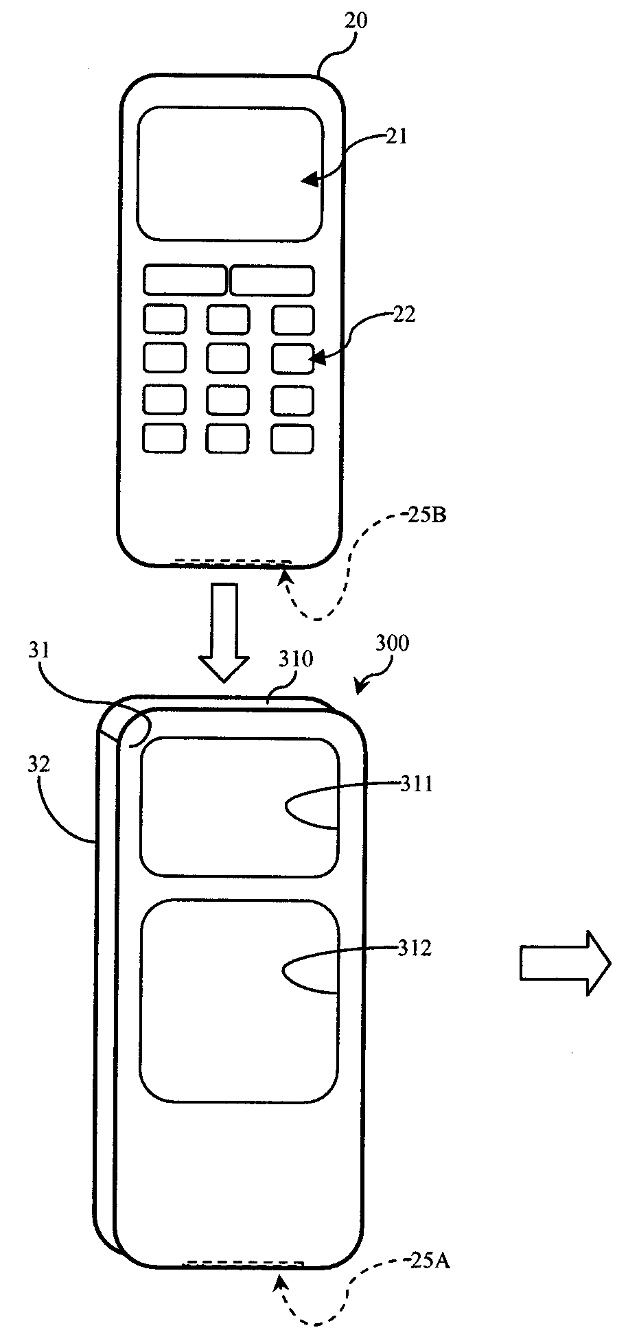
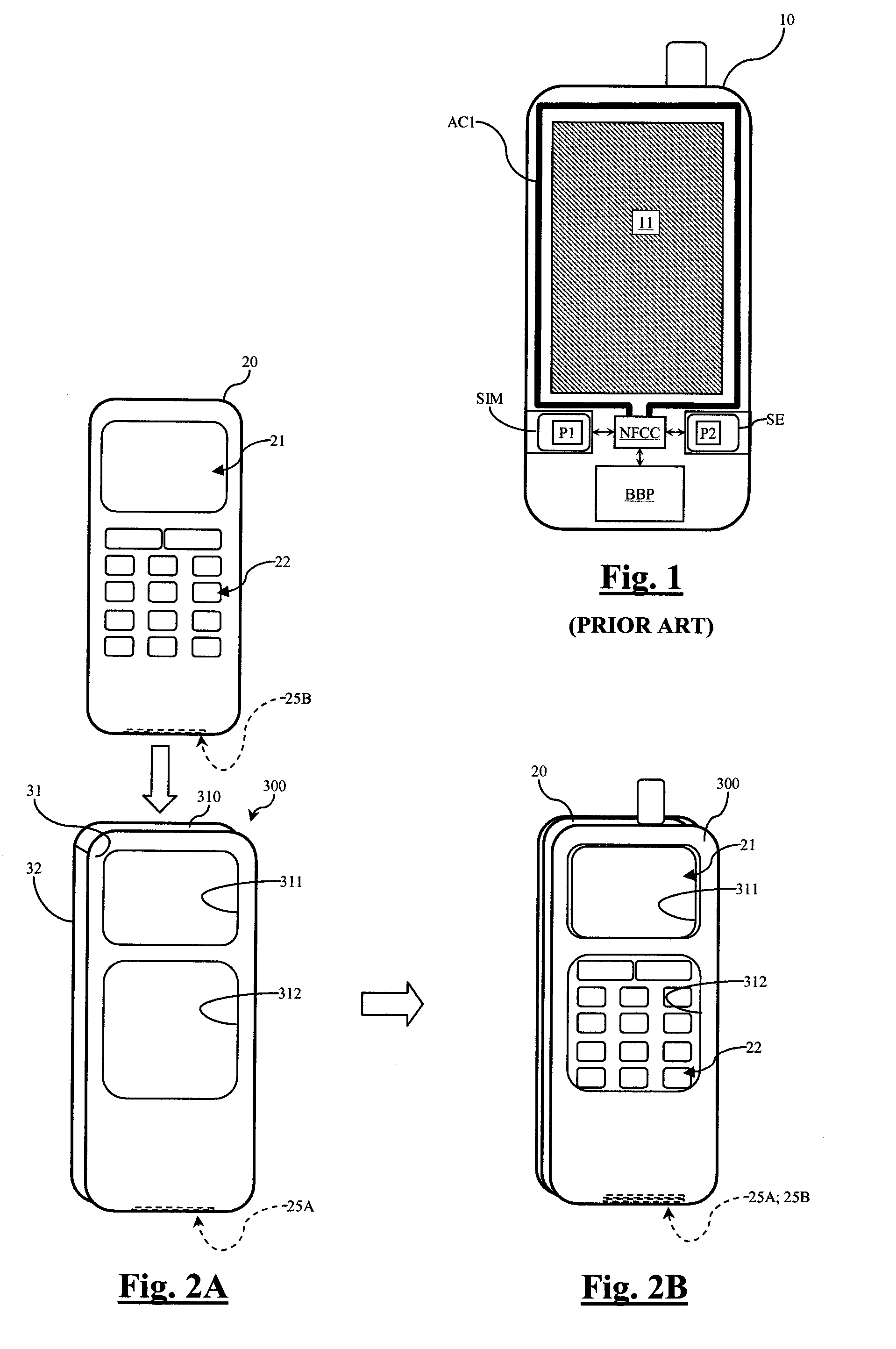
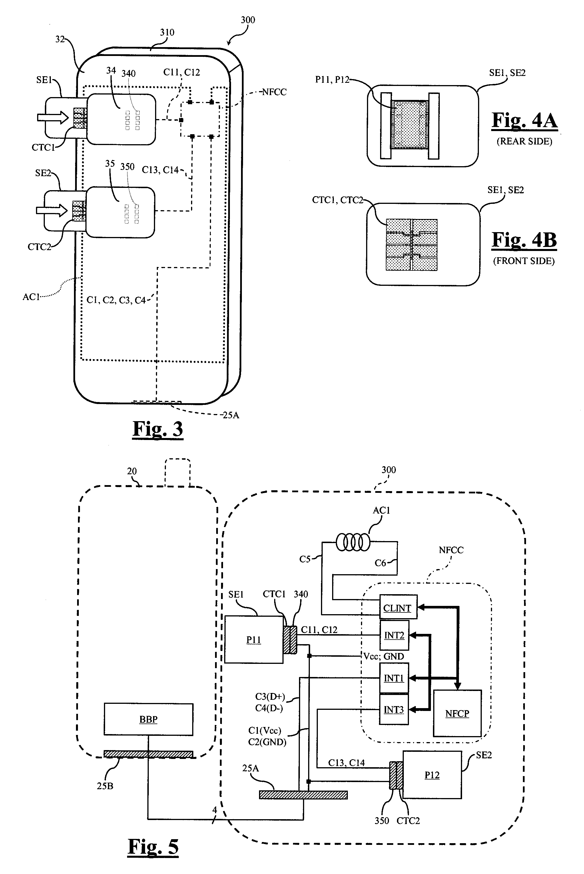
[0043]FIGS. 2A, 2B, and 3 show an embodiment 300 of a protective envelope according to the invention, designed to accommodate a mobile telephone 20. The protective envelope includes a front side 31 (FIGS. 2A, 2B), a rear side 32 (FIG. 3) and covers at least 40% of the telephone surface. An opening 310 is provided between the front side and the rear side so that the telephone 20 may be inserted into the envelope 300, as shown in FIGS. 2A, 2B. The front side 31 additionally includes an opening 311 allowing access to a screen 21 of the telephone 20 and an opening 312 allowing access to a keypad 22 of the telephone 20. The openings 311, 312 may be covered with a thin transparent material if protection against rain is desired. Other openings can be provided, such as to allow access to telephone buttons and / or connectors. In some embodiments, a single opening may be provided on the front side to accommodate a telephone without a keypad, equipped with a touch screen.
[0044]The protective en...
embodiment 301
[0057]FIG. 6 shows an embodiment 301 of the protective envelope which differs from that of FIG. 3 in that controller NFCC is no longer embedded in the envelope and in that a housing 33 is provided to receive the controller NFCC. The housing 33 includes an insertion slot, which includes a group of contacts 330 that are shown in FIG. 6 through the material of the protective envelope. The processor NFCC is embedded in a microcard NFCCARD, the front side of which comprises a group of contacts CTC3 which are connected to inputs / outputs of the controller NFCC. The controller NFCC is linked to conductors C1-C6 and C11-C14 through contacts of the group of contacts CTC3 and contacts of the group of contacts 330.
embodiment 302
[0058]FIG. 7 shows an embodiment 302 of the protective envelope which differs from that of FIG. 3 in that the protective envelope comprises housings 34′, 35′ without groups of contacts provided to accommodate contactless microcard SE1′, SE2′ respectively. Conductors C11 to C14 are also not present inside the envelope. Each microcard SE1′, SE2′ comprises, embedded therein, an auxiliary antenna coil ANT1, ANT2 instead of the groups of contacts CTC1, CTC2 and a processor P11′, P12′ connected to the auxiliary antenna coil ANT1, ANT2, respectively. Auxiliary antenna coils ANT1, ANT2 are schematically represented and may comprise one or more windings. In addition, antenna coil AC1 is replaced by an antenna coil AC2 which is designed to be inductively coupled with the auxiliary antenna coils ANT1, ANT2. Each processor P11′, P12′ is a contactless integrated circuit for example such as that commercialized by Inside Contactless under the designation Micropass®, which is generally embedded in ...
PUM
 Abstract
Description
Claims
Application Information
 - R&D
- Intellectual Property
- Life Sciences
- Materials
- Tech Scout
- Unparalleled Data Quality
- Higher Quality Content
- 60% Fewer Hallucinations
Browse by: Latest US Patents, China's latest patents, Technical Efficacy Thesaurus, Application Domain, Technology Topic, Popular Technical Reports.
© 2025 PatSnap. All rights reserved.Legal|Privacy policy|Modern Slavery Act Transparency Statement|Sitemap|About US| Contact US: help@patsnap.com


