Handheld Tactical Knife

Active Publication Date: 2010-04-29
HANSEN JEREMIAH +1
View PDF22 Cites 10 Cited by
  • Summary
  • Abstract
  • Description
  • Claims
  • Application Information

AI Technical Summary

Benefits of technology

[0013]In accordance with the invention, this present invention provides a tactical knife with an effective cutting edge, a penetrating tip, a more complex wound and a cross section optimized for strength. The knife is designed in such a way as to provide the user with an effective tool for tactical

Problems solved by technology

The straight edge on these knives makes an effective cutting and slashing tool, but lacks penetration power due to the wide profile.
This constant profile also can limit knife removal due to suction within the wound.
These knives are limited in their capacity to do additional damage that is more difficult to repair, such as tears, because of the sharpened edges.
The addition of serrations, while making the wound more grievous, might cause the knife to become caught in the wound, clothing, or armor.
The flat bladed knives also can bend and break if the force is sufficient perpendicular to the edge, limiting their durability.
Other weapons exist which penetrate well that are essentia

Method used


Image

  • Handheld Tactical Knife
  • Handheld Tactical Knife
  • Handheld Tactical Knife

Examples


Embodiment Construction

—PREFERRED EMBODIMENT—FIGS. 1, 2, 2A, 2B, 2C, 2D, 3, 4, AND 5

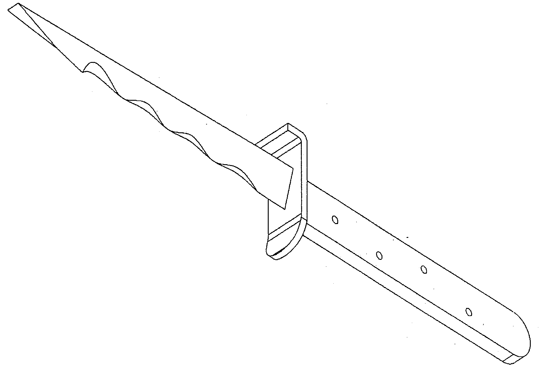
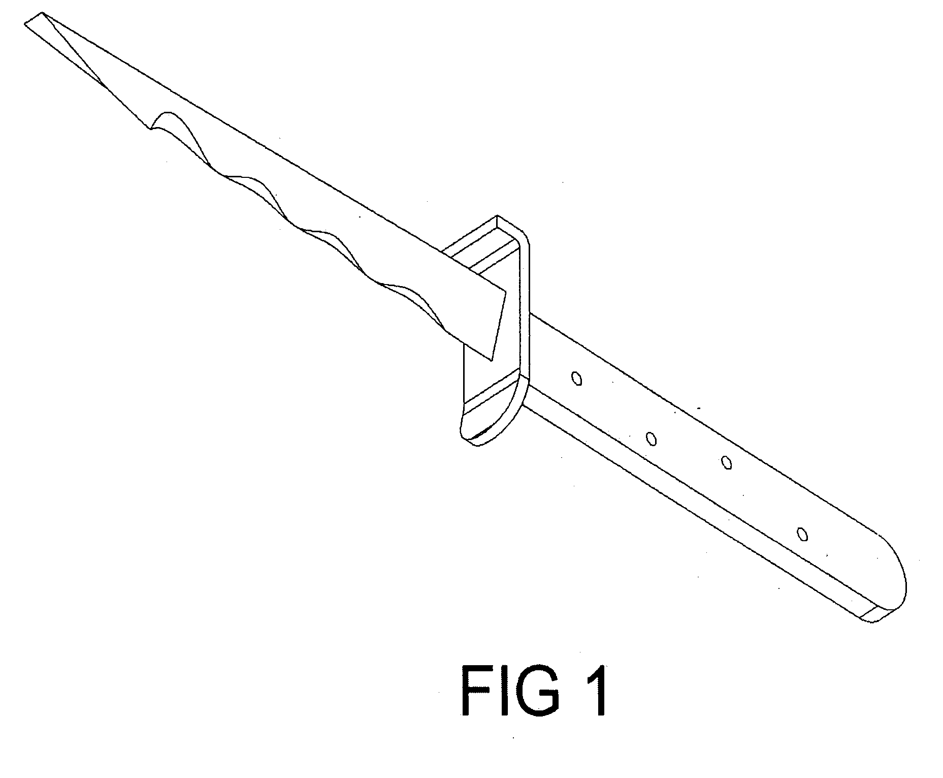
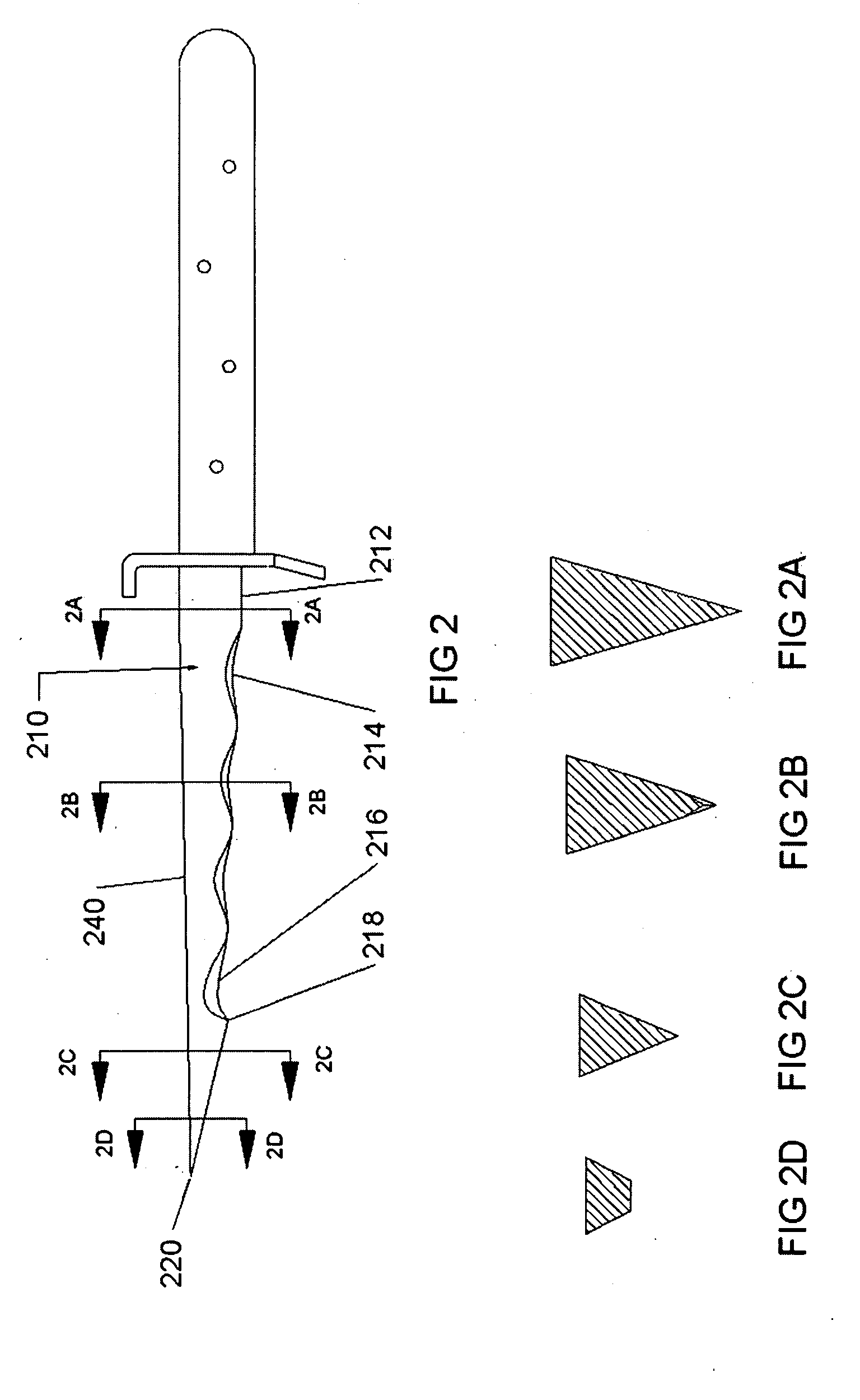
[0032]A preferred embodiment of the knife blade is shown in FIGS. 1, 2, 2A, 2B, 2C, 2D, 3, 4, and 5. A hilt and a handle are shown for illustration and orientation purposes in FIGS. 1, 2, 3, 4, and 5. FIG. 1 displays an isometric view of the preferred knife for perspective. FIG. 2 displays the side view of the knife. Knife blade 210 has an isosceles triangle cross section, shown in FIG. 2A. The preferred measurement of the cross section height from a short side to a tip is approximately 0.7 inches. In FIG. 2, the main cutting edge 212 is on the bottom of the blade. Scalloping 214 is cut into the cross section to improve cutting performance of the main blade. This cut into the cross section is displayed in FIG. 2B. Scalloping continues in a sinusoidal fashion for 3 iterations, then blends with the gut hook to create scalloped hook 216. Scalloped hook 216 transitions into the gut hook 218. From gut hook 218 to approximately ...


PUM


Abstract

Handheld tactical knife combining structural features of a structurally advantageous and stress distributing base cross section (FIG. 2A), a penetrating tip (220), tapers in perpendicular axis along the blade length (FIG. 2, FIG. 3), and a cutting edge (212). The preferred embodiment contains scallops (214), a gut hook (218), and a penetrating chisel-type tip (220).

Description

CROSS-REFERENCE TO RELATED APPLICATIONS[0001]Not ApplicableFEDERALLY SPONSORED RESEARCH[0002]Not ApplicableSEQUENCE LISTING OR PROGRAM[0003]Not ApplicableBACKGROUND OF THE INVENTION[0004]1. Field of Invention[0005]This invention relates to knives, specifically to tactical knives for hand-to-hand combat.[0006]2. Prior Art[0007]Prior art U.S. Pat. Nos. 7,228,633; 6,837,896; 5,322,277; 436,891; 822,456; 2,631,366; 2,566,112; 4,495,698; D220,930; D137,916; D482,426[0008]Tactical knives vary in layout and usually consist of a flat blade with one to both edges sharpened for an effective cutting edge. Some examples of this type can be seen in U.S. Pat. No. D482,426; U.S. Pat. No. D137,916; and U.S. Pat. No. D220,930. The straight edge on these knives makes an effective cutting and slashing tool, but lacks penetration power due to the wide profile. This constant profile also can limit knife removal due to suction within the wound. These knives are limited in their capacity to do additional ...

Claims


Application Information

Patent Timeline
IPC IPC(8): B26B9/02B26B3/00
CPCB26B3/00F41B13/08B26B9/02
Inventor HANSEN, JEREMIAH JOHNDELLA-PENNA, THOMAS JOHN
Owner HANSEN JEREMIAH
Why Eureka
Try Eureka