Sterilization apparatus for fabric and shoes

a technology of sterilization apparatus and fabric, which is applied in the field of sterilization apparatus for fabric and shoes, can solve the problems that conventional coat hangers cannot be used to inhibit and achieve the effect of preventing the growth of bacteria or fungus

Inactive Publication Date: 2010-04-29
CHUNG-SHAN INSTITUTE OF SCIENCE & TECHNOLOGY; MINISTRY OF NATIONAL DEFENSE
View PDF6 Cites 9 Cited by
  • Summary
  • Abstract
  • Description
  • Claims
  • Application Information

AI Technical Summary

Problems solved by technology

However, the conventional coat hangers can not be u

Method used


Image

  • Sterilization apparatus for fabric and shoes
  • Sterilization apparatus for fabric and shoes
  • Sterilization apparatus for fabric and shoes

Examples


Embodiment Construction

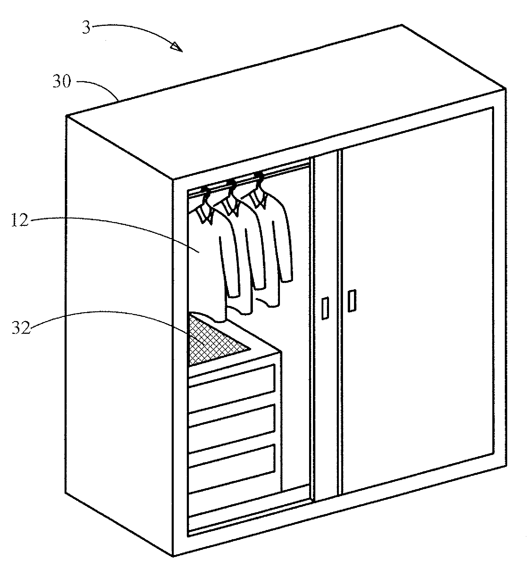
[0020]In the prior art, the organization member, such as a wardrobe, a coat hanger, a shoes cabinet or other organization members, is used for containing or hanging fabrics and / or shoes. However, the conventional coat hangers can not be used for inhibiting the growth of bacteria or fungus. Accordingly, the sterilization apparatus of the invention can be used for solving said problem.

[0021]The sterilization apparatus of the invention can be used for organizing fabrics and shoes. The sterilization apparatus includes an organization member, such as a wardrobe, a coat hanger or a shoes cabinet. Moreover, the sterilization apparatus further includes a light sterilization type member disposed with the organization member.

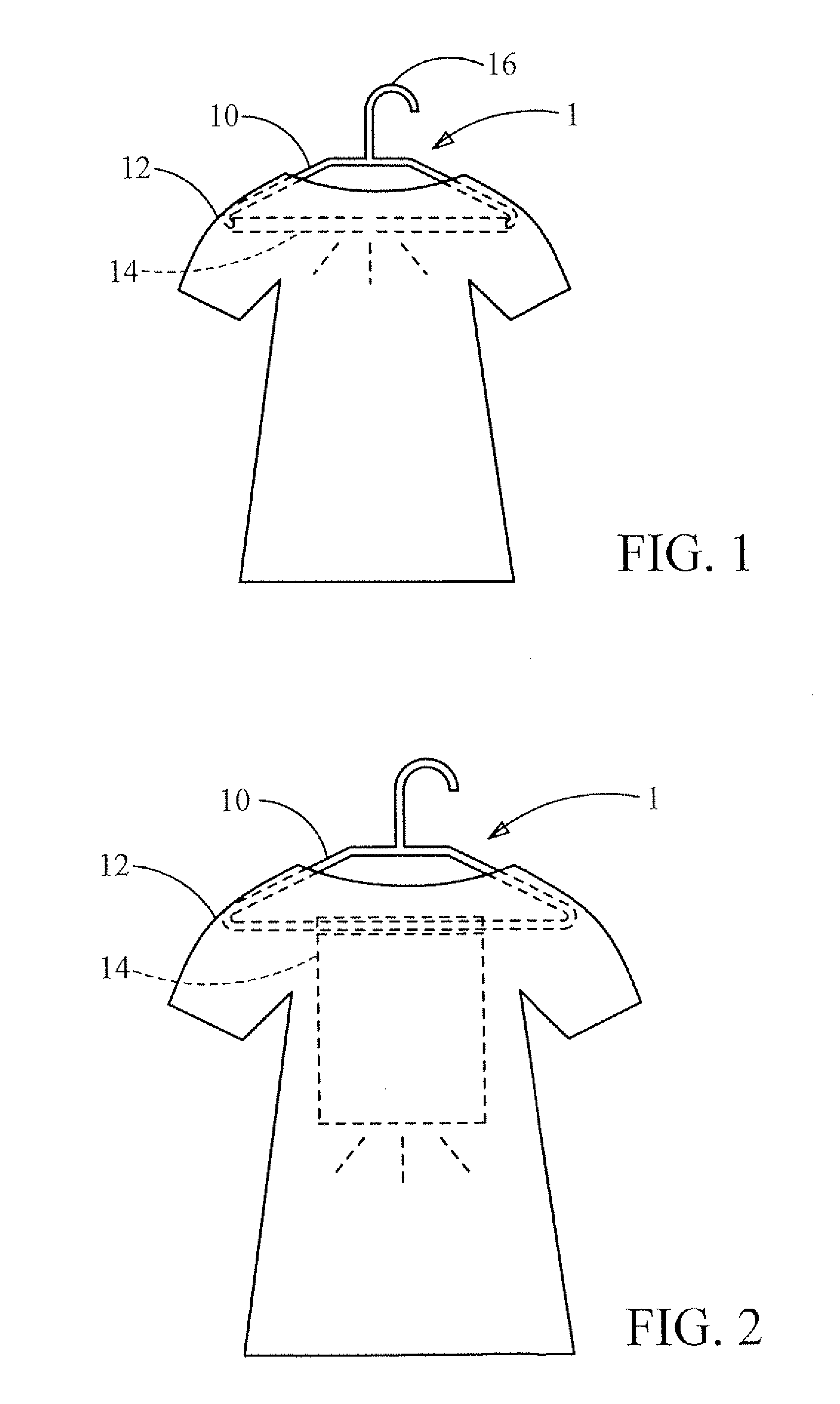
[0022]Please refer to FIG. 1, which illustrates the structure of a sterilization apparatus with a sterilization member of a preferred embodiment of the invention. As shown in FIG. 1, the sterilization apparatus 1 of the invention includes the coat hanger 10 and the light ...


PUM


Abstract

The invention discloses a sterilization apparatus for a fabric and shoes. The sterilization apparatus of the invention includes an organization member for containing the fabric or shoes. The sterilization apparatus of the invention further includes a light sterilization type member and/or an exsiccating member disposed with the organization member for sterilizing or drying the fabric or shoes.

Description

BACKGROUND OF THE INVENTION[0001]1. Field of the Invention[0002]The present invention relates generally to a sterilization apparatus for fabric and shoes, and more particularly, to a sterilization apparatus including a light sterilization type member and / or an exsiccating member for sterilizing or drying the fabric or shoes.[0003]2. Description of the Prior Art[0004]Today's wire coat hanger was inspired by a clothes hook patented in 1869, by O. A. North. Albert J. Parkhouse, an employee of Timberlake Wire and Novelty Company in Jackson, created a coat hanger in 1903 and granted a patent about the coat hanger, in response to co-workers' complaints of too few coat hooks.[0005]For example, TW Pat. No. M321265 entitled “COAT HANGER” disclosed a quadrangular coat hanger which includes a main body and a rotating body. The main body has a hanging portion. At least one pivot base, having at least a hole and a bump, is disposed on each sides of the main body. The bump is disposed on the outs...

Claims


Application Information

Patent Timeline
IPC IPC(8): A61L2/08A61L2/10
CPCA47L23/00A61L2/04D06M10/001A61L2/10A61L2202/26A61L2/085
Inventor CHANG, KUO-JENWU, KUN-CHIA
Owner CHUNG-SHAN INSTITUTE OF SCIENCE & TECHNOLOGY; MINISTRY OF NATIONAL DEFENSE
Why Eureka
Try Eureka