Insulation type ac-DC converter and LED DC power supply device using the same

a technology of led dc power supply and ac-dc converter, which is applied in the direction of electric variable regulation, process and machine control, instruments, etc., can solve the problems of increasing circuit losses, and affecting the operation of circuits

Active Publication Date: 2010-05-06
MATSUSHITA ELECTRIC WORKS LTD
View PDF10 Cites 68 Cited by
  • Summary
  • Abstract
  • Description
  • Claims
  • Application Information

AI Technical Summary

Benefits of technology

[0026]Through such a configuration, advantageous result...

Problems solved by technology

By raising the switching frequency used in AC-DC converters which obtain a desired DC power from a commercial power supply, it is possible to reduce the sizes of the transformers, inductors, and other components used; but as the switching frequency is raised, increased switching losses and other circuit losses pose problems, and various circuit-related innovations are being made to improve efficiency.
As a result, when an attempt is made to compensate the output in response to large-amplitude load fluctuations, fluctuations in the voltage of the commercial power supply, or other broad-range fluctuations, it becomes extremely difficult to maintain multi-resonance waveforms, and ultimately there is the problem tha...

Method used


Image

  • Insulation type ac-DC converter and LED DC power supply device using the same
  • Insulation type ac-DC converter and LED DC power supply device using the same
  • Insulation type ac-DC converter and LED DC power supply device using the same

Examples


example 1

Practical Example 1

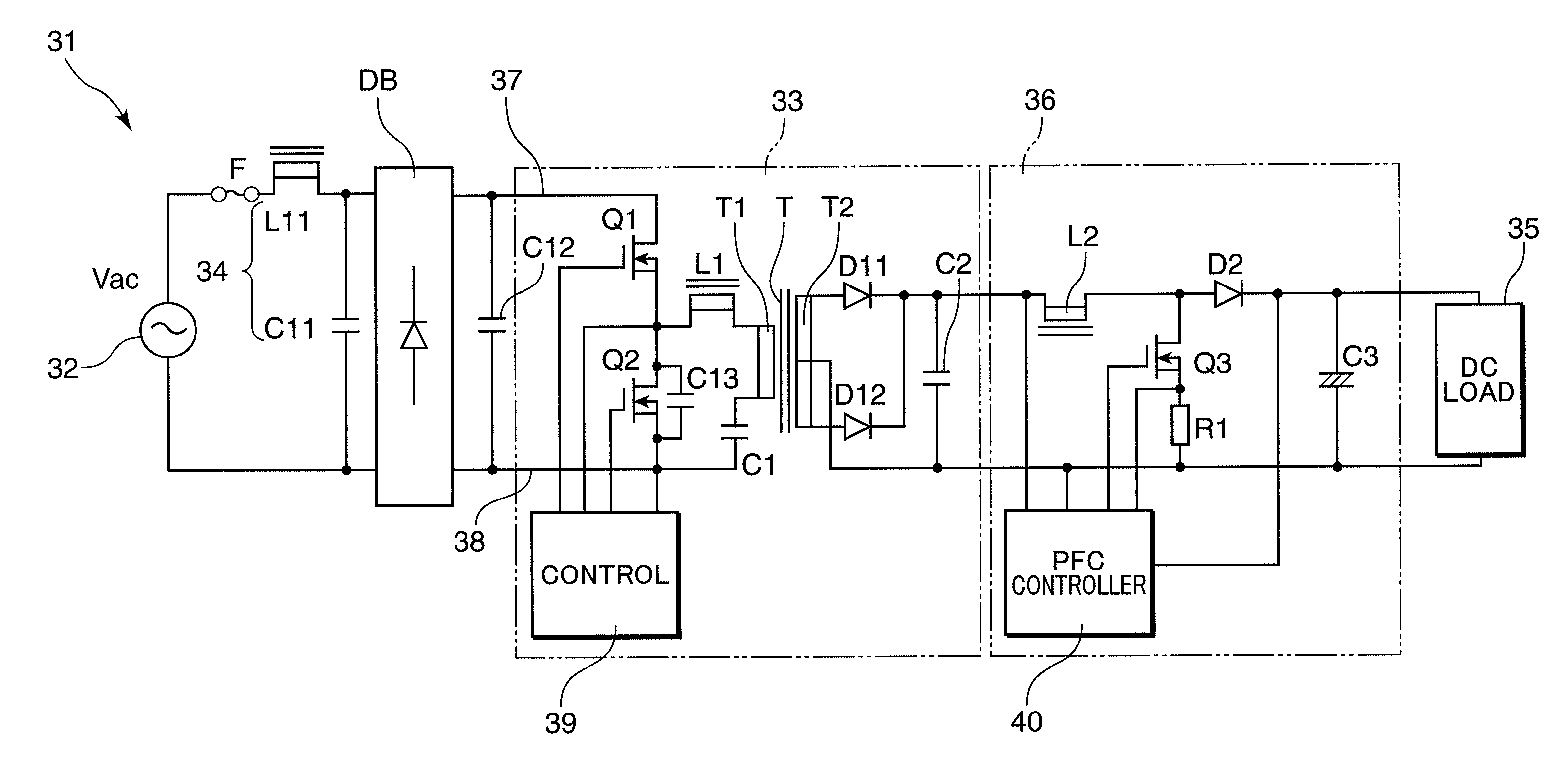
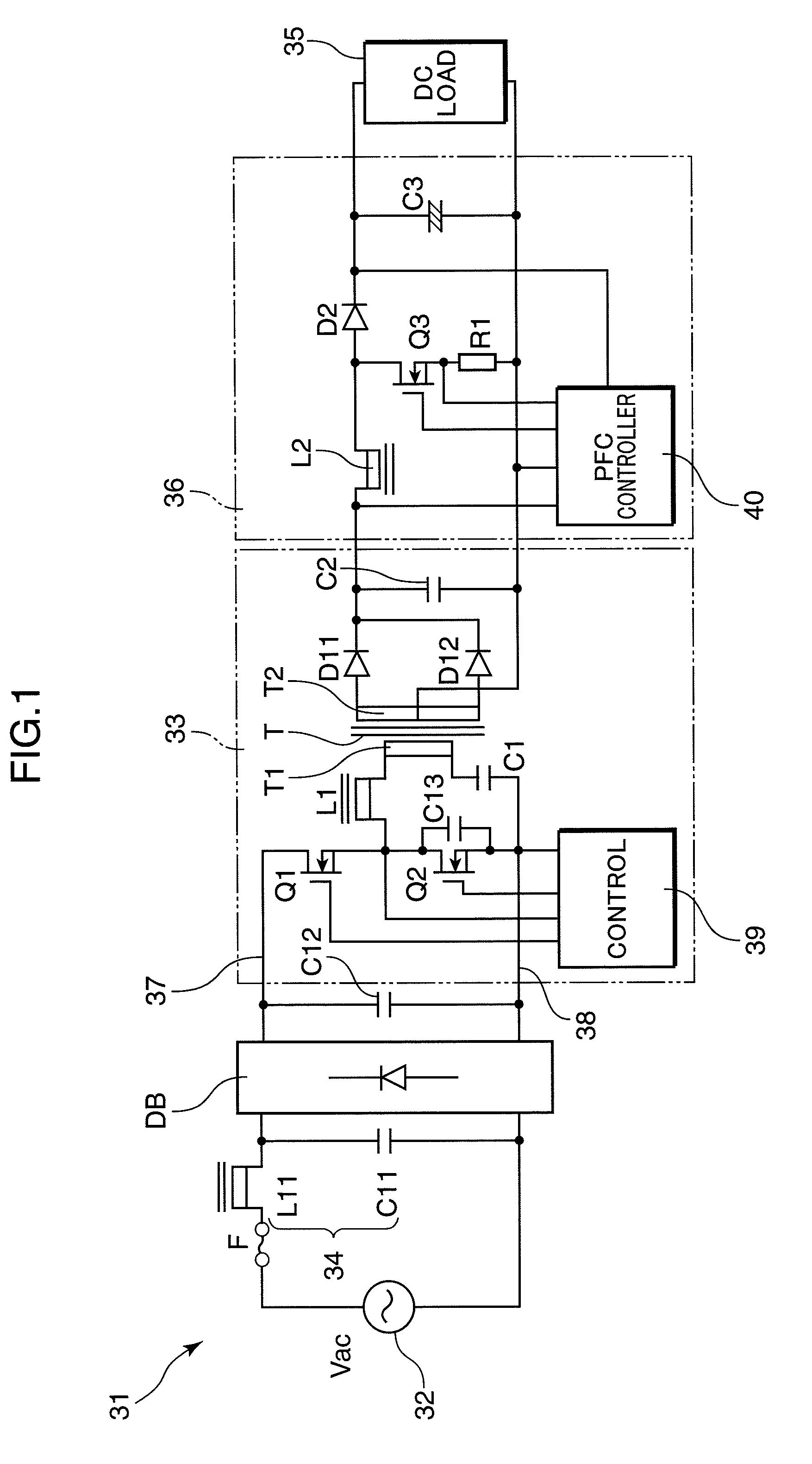
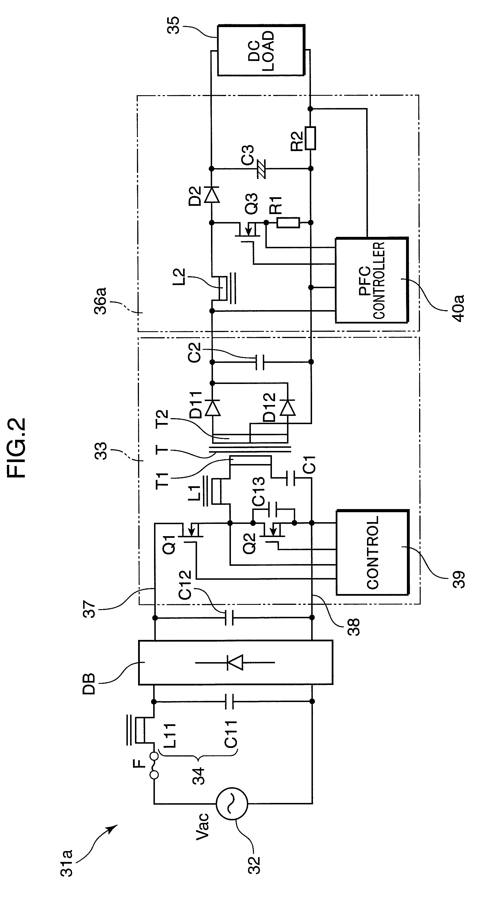
[0041]FIG. 1 and FIG. 2 are block diagrams showing the electrical configurations of insulation type AC-DC converters 31 and 31a of a first aspect of the invention. The converter 31 is substantially configured comprising a diode bridge DB, which is full-wave rectifying means performing full-wave rectification of an input current from a commercial power supply 32; a multi-resonance type half-bridge DC-DC converter 33, which is a first converter, provided in the stage after the diode bridge DB, having an insulation transformer T; a filter circuit 34, provided between the commercial power supply 32 and the half-bridge DC-DC converter 33, which smoothes the input current comprising high-frequency components; and, a boosting chopper circuit 36, which is a second converter, provided in the stage after the half-bridge DC-DC converter 33, which provides a DC voltage stabilized at a desired voltage to a DC load 35, and is provided to improve the power factor.

[0042]The sinus...

example 2

Practical Example 2

[0056]FIG. 6 is a block diagram showing the electrical configuration of the boosting chopper circuit 46 in the insulation type AC-DC converter of a second aspect of the invention. In this AC-DC converter, the configuration other than the boosting chopper circuit 46 is similar to that of the AC-DC converters 31 and 31a of FIG. 1 and FIG. 2 described above, and an explanation is omitted. The boosting chopper circuit 46 is similar to the above-described boosting chopper circuit 36, and the same reference symbols are assigned to corresponding portions, explanations of which are omitted. It should be noted that in this boosting chopper circuit 46, the second choke coil L2 comprises the primary winding T101 of the transformer T10, and the voltage induced in the auxiliary winding T102 thereof is input to the control circuit 50. Also, the control circuit 50 detects the current I101 flowing in the primary winding T101 which are the second choke coil, and when the current I...

example 3

Practical Example 3

[0059]FIG. 8 is a block diagram showing the electrical configuration of the half-bridge DC-DC converter 53 in the insulation type AC-DC converter of a third aspect of the invention. In this AC-DC converter, the configuration other than the DC-DC converter 53 is the same as in the AC-DC converters 31 and 31a of FIG. 1 and FIG. 2 above, and explanations are omitted. The DC-DC converter 53 is similar to the above-described DC-DC converter 33, and the same reference symbols are assigned to corresponding portions, with explanations thereof omitted. It should be noted that in this DC-DC converter 53, the first choke coil L1 and insulation transformer T are formed by a single leakage transformer T′.

[0060]That is, by reducing the coupling between winding of the above-described insulation transformer T to generate leakage inductance, when forming the series resonance circuit, the primary winding T1′ of the leakage transformer T′ can also be made to function as the first ch...


PUM


Abstract

In an insulation type AC-dc converter in which input current from a commercial power supply is converted to obtain insulated direct current, the overall efficiency is raised and the structure is simplified. A multi-resonance type half-bridge DC-DC converter having an insulation transformer T is used as a first converter, and a boosting chopper circuit for power factor improvement is used as a second converter. Hence through multi-resonance operation, increases in losses can be suppressed even when the switching frequency is raised, and because a half-bridge circuit is used, switching elements and similar with lower voltage ratings can be employed, whereby overall efficiency can be increased. Moreover, a voltage substantially similar to the full-wave rectified waveform of the power supply voltage is obtained from the output capacitor at the boosting chopper circuit input, whereby there is no need for a feed-forward circuit across the insulation transformer, and moreover the electrolytic capacitor which had to be provided on the converter input side is unnecessary. This is advantageous for achieving miniaturization and a thin design.

Description

TECHNICAL FIELD[0001]The present invention relates to an insulation type AC-DC converter which converts input current from a commercial power supply to a high frequency and obtains insulated DC current, and to a DC power supply device for LEDs which uses such a converter, and in particular relates to a high-efficiency converter with an improved power factor.BACKGROUND ART[0002]By raising the switching frequency used in AC-DC converters which obtain a desired DC power from a commercial power supply, it is possible to reduce the sizes of the transformers, inductors, and other components used; but as the switching frequency is raised, increased switching losses and other circuit losses pose problems, and various circuit-related innovations are being made to improve efficiency.[0003]Current resonance (multi-resonance) type AC-DC converters, such as that described in Patent Document 1, are known as insulation type AC-DC converter technology of the prior art which can suppress switching l...

Claims


Application Information

Patent Timeline
IPC IPC(8): H05B41/36H02M3/335
CPCH02M1/4208H02M3/337H02M2001/007H05B33/0815Y02B20/348Y02B70/126H02M2001/0058Y02B70/1491H05B45/355Y02B20/30Y02B70/10H05B45/39H05B45/38H05B45/382H02M1/0058H02M1/007H02M3/33571H02M3/01
Inventor NISHINO, HIROYUKISHIOHAMA, EIJI
Owner MATSUSHITA ELECTRIC WORKS LTD
Why Eureka
Try Eureka