Surface contact card retention assembly

Inactive Publication Date: 2010-05-06
HONG FU JIN PRECISION IND (SHENZHEN) CO LTD +1
10 Cites 3 Cited by

AI-Extracted Technical Summary

Problems solved by technology

As a result, the SIM card will not be sufficiently connected with the connector 80 or released from the receiving g...

Abstract

A retention assembly for securing a surface contact card in a portable electronic device includes a main body defining a receiving groove in the main body, and a locking member slidably positioned on the main body adjacent to the receiving groove. The locking member is slidable from a first position at a side of the receiving groove to a second position on a top of the receiving groove, and is latched at the second position, thereby pressing opposite ends of the surface contact card.

Application Domain

Engagement/disengagement of coupling partsConveying record carriers +6

Technology Topic

EngineeringMechanical engineering

Image

  • Surface contact card retention assembly
  • Surface contact card retention assembly
  • Surface contact card retention assembly

Examples

  • Experimental program(1)

Example

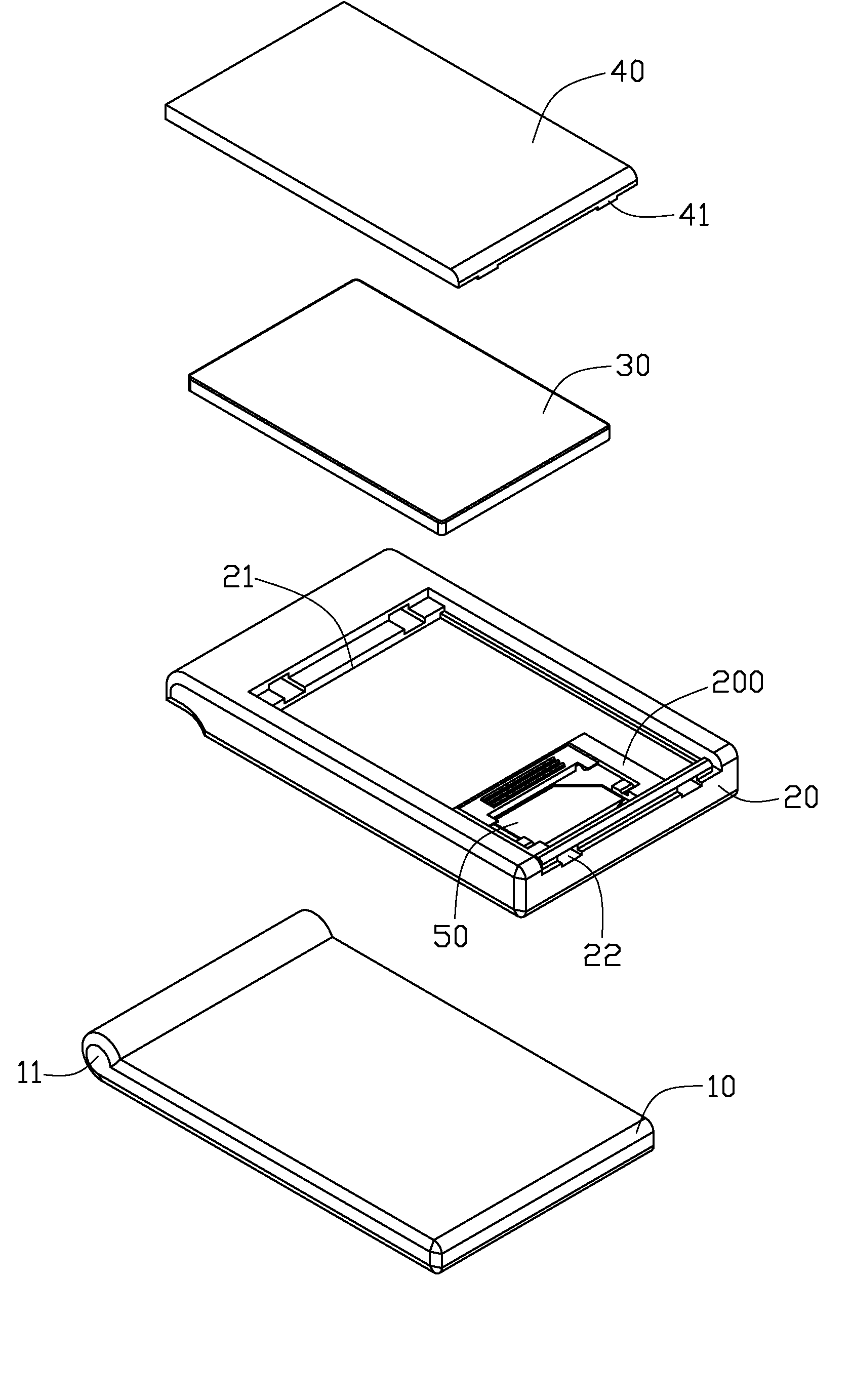
[0016]The present retention assembly may be used for securing a surface contact card in a portable electronic device. Hereinafter, for the purposes of conveniently describing the embodiments of the retention assembly, the retention assembly as used for securing a SIM card in a mobile phone is described and illustrated.
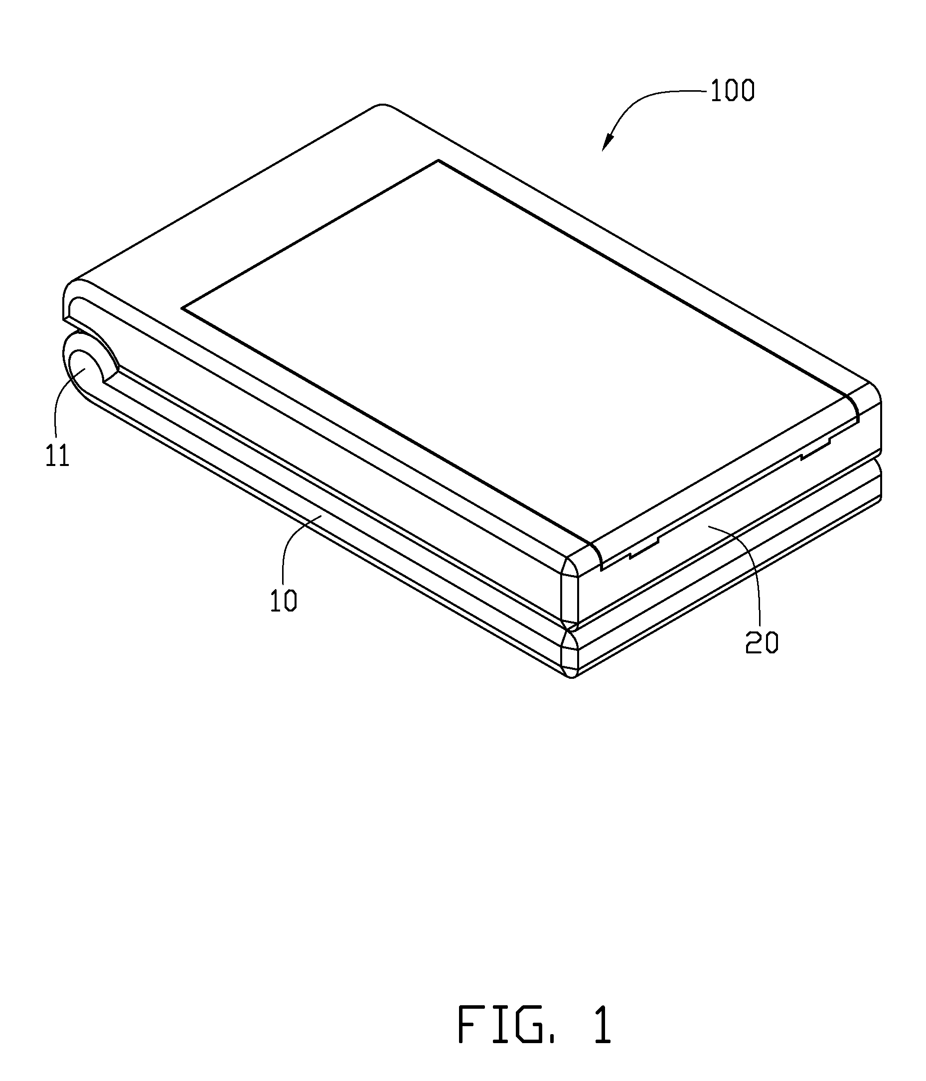
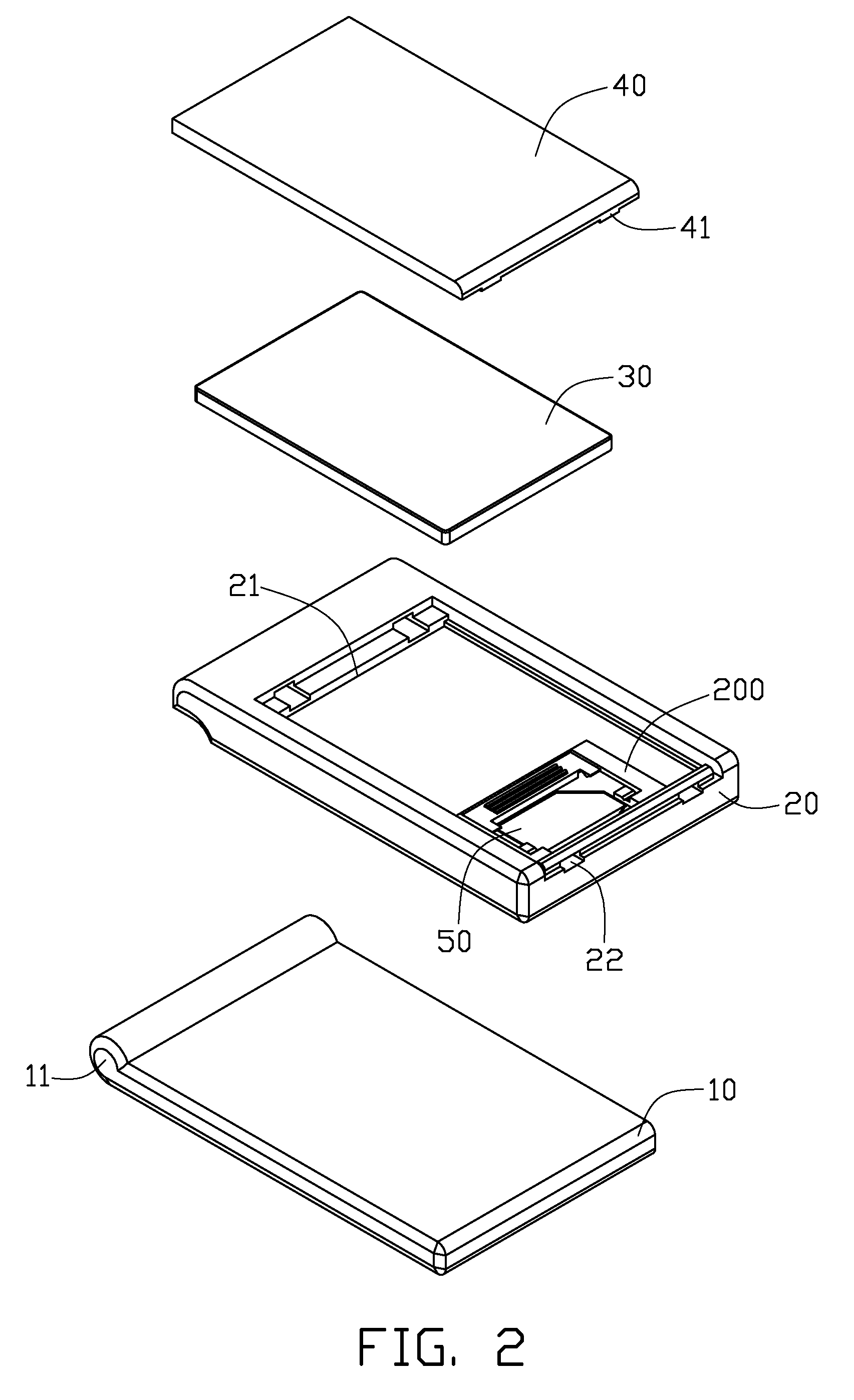
[0017]Referring to FIGS. 1 and 2, an embodiment of a mobile phone 100 includes a first main body 10, a second main body 20, a battery 30, a battery cover 40, a SIM card 50, and an embodiment of a retention assembly 200. The second main body 20 is pivotally connected to the first main body 10 via a hinge 11. The second main body 20 defines a battery groove 21 to receive the battery 30, and a plurality of latching grooves 22 adjacent to the battery groove 21. The battery cover 40 forms a plurality of latching hooks 41 to engage in the latching grooves 22 of the second main body 20, thus shielding the battery 30. The SIM card 50 is secured in the battery groove 21 by the retention assembly 200.
[0018]Referring to FIG. 3, the retention assembly 200 includes a pair of fixing members 25, and a locking member 27. A mounting groove 23 is defined in a bottom surface of the battery groove 21, to receive the fixing members 25 and the locking member 27. A receiving groove 231 is defined in a bottom surface of the mounting groove 23, to receive the SIM card 50.
[0019]A plurality of contacts 233 are positioned on a bottom surface of the receiving groove 231. The contacts 233 may be metallic elastic pieces. The receiving groove 231 has a shape substantially the same as a shape of the SIM card 50, so that the SIM card 50 can be received in the receiving groove 231 and electrically connected to the contacts 233. A depth of the receiving groove 231 is substantially equal to a thickness of the SIM card 50. In one embodiment, the bottom surface of the mounting groove 23 also defines an arched groove 232 (shown in FIG. 4) communicating with the receiving groove 231, to facilitate assembling or disassembling the SIM card 50 from the receiving groove 231.
[0020]Each fixing member 25 is substantially L-shaped, and includes a limiting portion 251 and a connecting portion 252 extending substantially perpendicularly from a side of the limiting portion 251. The limiting portion 251 defines a recess 2511 in a bottom surface of the limiting portion 251. Thus, when the fixing member 25 is fixed in the mounting groove 23, the limiting portion 251 and the bottom surface of the mounting groove 23 cooperatively define a sliding groove 253 (shown in FIG. 4). Alternatively, the sliding groove 253 may be directly defined in the limiting portion 251. The connecting portion 252 has a stepped surface 2521, and defines a latching groove 2522 in the stepped surface 2521. In an alternative embodiment, the pair of the fixing members 25 may be integrally formed with the second main body 20.
[0021]The locking member 27 may be a substantially elongated plate, and includes two sliding blocks 271 formed on opposite ends of the locking member 27. A thickness of the sliding block 271 is substantially equal to or smaller than a height of the sliding groove 253, such that the sliding block 271 is slidable in the sliding groove 253. The locking member 27 further includes two positioning portions 272 formed on a side of the locking member 27. The positioning portions 272 are adjacent to the sliding block 271, and each positioning portion 272 forms a latching protrusion 2721 on a bottom surface of the positioning portion 272 to engage in the latching groove 2522. Alternatively, the latching protrusion 2721 may be formed on the stepped surface 2521, and the latching groove 2522 may be defined in the bottom surface of the positioning portion 272. A handling portion 273 is formed on a top surface of the locking member 27 to facilitate operation of the locking member 27. In the illustrated embodiment, the handling portion 273 is a plurality of protruding ribs. In an alternative embodiment, the handling portion 273 may be other desired structures, such as a rough area, or a groove.
[0022]Referring also to FIG. 4, the fixing members 25 are fixed in two ends of the mounting groove 23. The sliding blocks 271 of the locking member 27 are slidably inserted in the sliding grooves 253. Initially, the locking member 27 is positioned at a side of the receiving groove 231, the SIM card 50 is positioned in the receiving groove 231.
[0023]Referring also to FIG. 5, the handling portion 273 may be pushed by an external force, so that the sliding blocks 271 slide along the sliding grooves 253. The locking member 27 moves along the direction as indicated by the arrow, until the latching protrusions 2721 of the locking member 27 engage in the latching grooves 2522 of the fixing members 25, and the locking member 27 is positioned on a top of the receiving groove 231, and pressing opposite ends of the SIM card 50. Therefore, the SIM card 50 is secured in the receiving groove 231 via a force created by the locking member 27 and the elastic force created by the contacts 233. The SIM card 50 is reliably secured in the receiving groove 231 because the opposite ends of the SIM card 50 are pressed by the locking member 27. Moreover, the locking member 27 is firmly latched on the fixing members 25, so that the locking member 27 has a good shock resistance capability.
[0024]The SIM card 50 can be easily removed from the receiving groove 231 by pushing the locking member 27 towards the sides of the receiving groove 231. The SIM card 50 is partially pushed out of the receiving groove 231 by the elastic force created by the contacts 233.
[0025]In other alternative embodiments, the sliding grooves 253 may be defined in opposite sidewalls of the mounting groove 23. Two latching portions having the latching grooves 2522 may be formed on the bottom surface of the mounting groove 23 adjacent to the receiving groove 231. Thus, the pair of fixing members 25 may be omitted.
[0026]It is believed that the present embodiments and their advantages will be understood from the foregoing description, and it will be apparent that various changes may be made thereto without departing from the spirit and scope of the embodiments or sacrificing all of its material advantages.

PUM

no PUM

Description & Claims & Application Information

We can also present the details of the Description, Claims and Application information to help users get a comprehensive understanding of the technical details of the patent, such as background art, summary of invention, brief description of drawings, description of embodiments, and other original content. On the other hand, users can also determine the specific scope of protection of the technology through the list of claims; as well as understand the changes in the life cycle of the technology with the presentation of the patent timeline. Login to view more.
Why Eureka
Try Eureka