Insertion Coupling Coaxial Connector

a coaxial cable and coupling technology, applied in the direction of coupling devices, two-pole connections, coupling devices, etc., can solve the problems of increasing manufacturing costs and installation time requirements, crimping and/or compression becomes impractical with larger diameter coaxial cables

Active Publication Date: 2010-05-06
COMMSCOPE TECH LLC
View PDF26 Cites 38 Cited by
  • Summary
  • Abstract
  • Description
  • Claims
  • Application Information

AI Technical Summary

Problems solved by technology

Machine threaded coupling surfaces between the metal body and the coupling nut of U.S. Pat. No. 5,795,188 and similarly configured prior coaxial connectors significantly increase manufacturing costs and installation time requirements.
Another drawback is the requirement for connector disassembly, sliding the back body over the cable end and then performing a precision cable end flaring op

Method used


Image

  • Insertion Coupling Coaxial Connector
  • Insertion Coupling Coaxial Connector
  • Insertion Coupling Coaxial Connector

Examples


Embodiment Construction

[0036]The inventor has analyzed available solid outer conductor coaxial connectors and recognized the drawbacks of threaded inter-body connection(s), manual flaring installation procedures and crimp / compression coaxial connector designs.

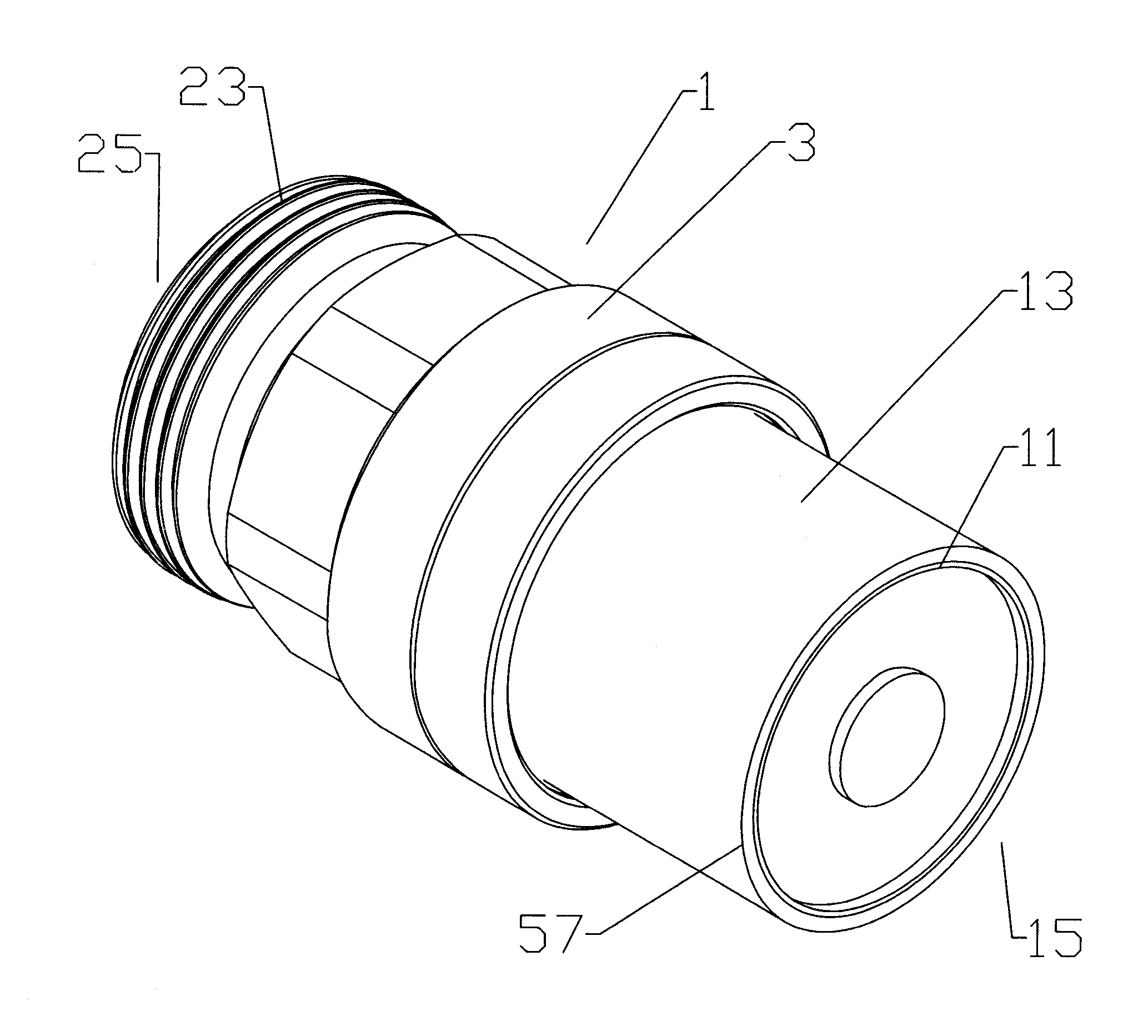
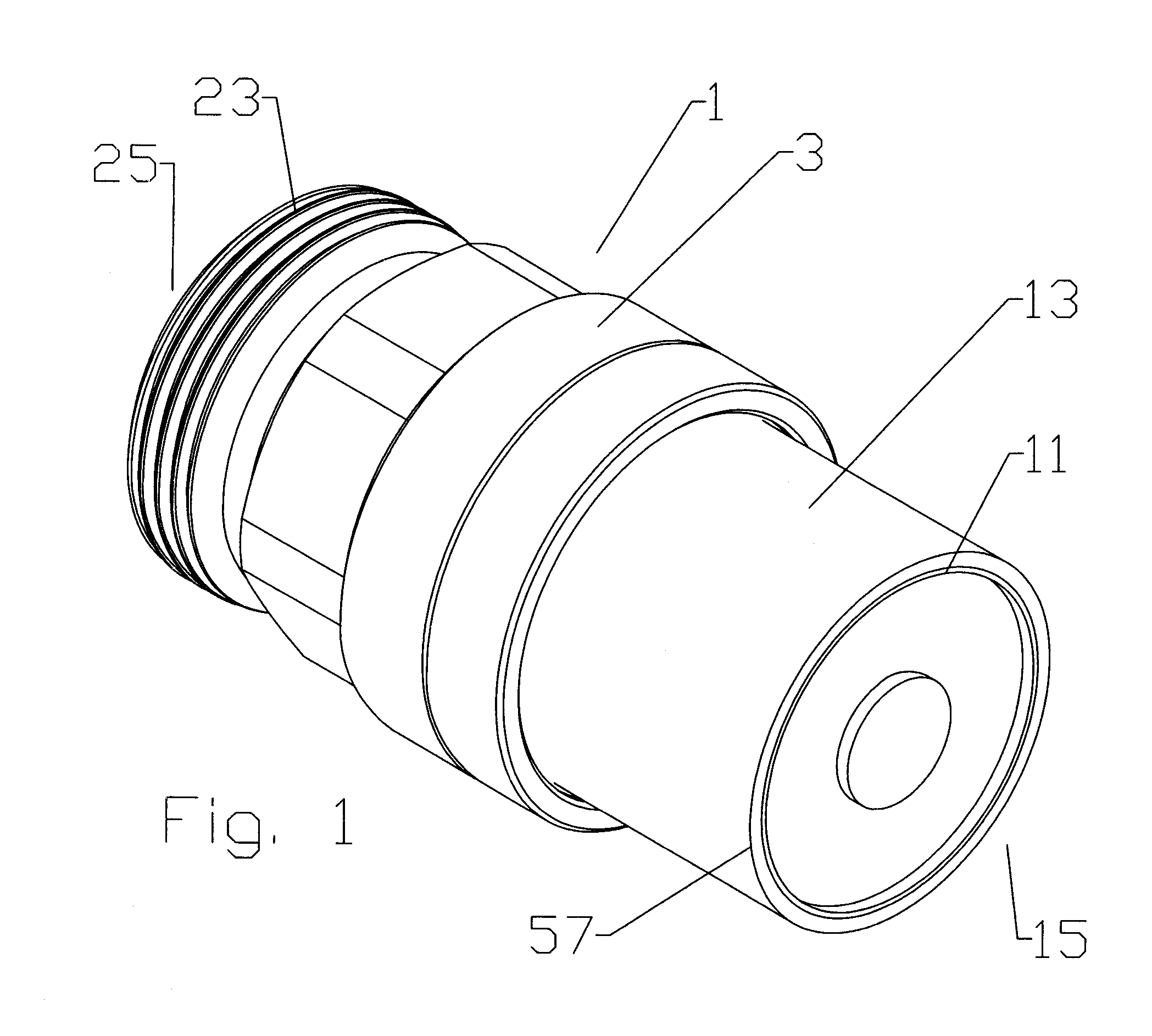
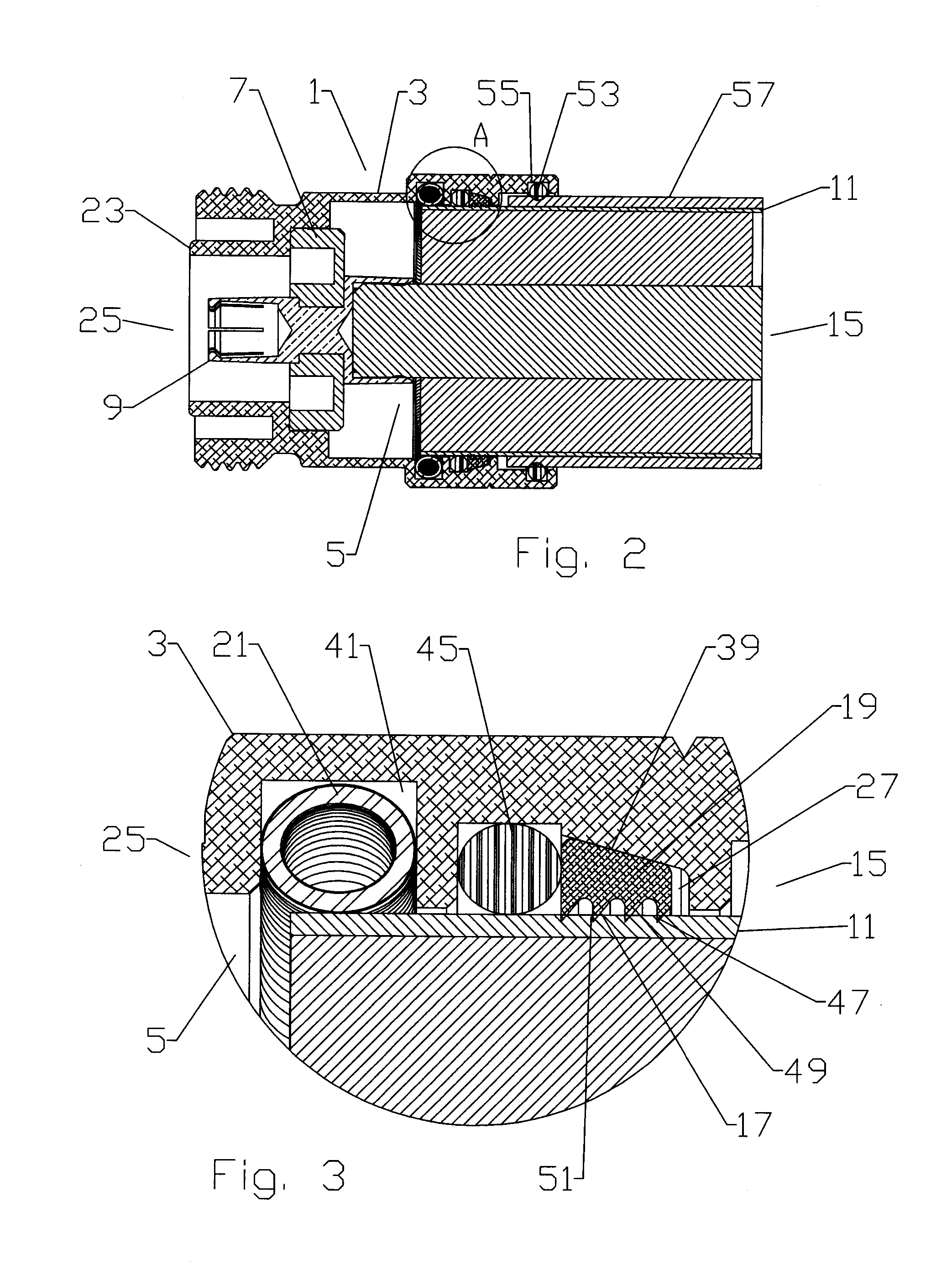
[0037]As shown in a first exemplary embodiment in FIGS. 1-3, a coaxial connector 1 according to the invention has a connector body 3 with a connector body bore 5. An insulator 7 seated within the connector body bore 5 supports an inner contact 9 coaxial with the connector body bore 5. The coaxial connector 1 mechanically retains the outer conductor 11 of a coaxial cable 13 inserted into the cable end 15 of the connector body bore 5 via a grip surface 17 located on the inner diameter of a grip ring 19. A spring contact 21 seated within the connector body bore 5 makes circumferential contact with the outer conductor 11, electrically coupling the outer conductor 11 across the connector body 3 to a connector interface 23 at the connector end 25.

[0038]The...


PUM

PropertyMeasurementUnit
Diameteraaaaaaaaaa
Corrugated surfaceaaaaaaaaaa

Abstract

A coaxial connector with a connector body is provided with a connector body bore. A grip ring is retained within the connector body bore, and an outer diameter of the grip ring abuts an annular wedge surface provided with a taper between a maximum diameter proximate the connector end and a minimum diameter proximate the cable end. The wedge surface may be provided directly on the connector body bore sidewall or alternatively on an inner diameter of a clamp ring coupled to the cable end of the connector body. An inner diameter of the grip ring is provided with a grip surface. A spring contact is retained within the connector body bore. The grip surface and an inner diameter of the spring contact are dimensioned to receive the outer conductor from the cable end there through and to then couple with an outer diameter of the outer conductor.

Description

CROSS REFERENCE TO RELATED APPLICATIONS [0001]This application is a continuation-in-part of commonly owned co-pending U.S. Utility patent application Ser. No. 12 / 264,932, titled “Insertion Coupling Coaxial Connector”, filed Nov. 5, 2008 by Jeffrey Paynter and Al Cox, hereby incorporated by reference in its entirety.BACKGROUND[0002]1. Field of the Invention[0003]This invention relates to electrical cable connectors. More particularly, the invention relates to a solid outer conductor coaxial cable connector coupled to a coaxial cable by insertion of the cable end into a connector body bore.[0004]2. Description of Related Art[0005]Coaxial cable connectors are used, for example, in communication systems requiring a high level of precision and reliability.[0006]To create a secure mechanical and optimized electrical interconnection between the cable and the connector, it is desirable to have generally uniform, circumferential contact between a leading edge of the coaxial cable outer condu...

Claims


Application Information

Patent Timeline
IPC IPC(8): H01R9/05
CPCH01R4/4818H01R9/0521H01R9/0527H01R13/187H01R13/5205Y10T29/49208H01R13/65802H01R24/40H01R24/564H01R2103/00H01R13/5804H01R4/48185
Inventor PAYNTER, JEFFERYCOX, AL
Owner COMMSCOPE TECH LLC
Why Eureka
Try Eureka