Constant velocity ball joint in the form of a counter track joint

a constant velocity ball joint and counter track technology, applied in the direction of yielding couplings, couplings, mechanical equipment, etc., can solve the problems of increasing noise development, increasing noise development, and even a risk of component failure, so as to achieve a large articulation angle and increase noise development

Active Publication Date: 2010-05-06
GKN DRIVELINE INT GMBH
View PDF1 Cites 4 Cited by
  • Summary
  • Abstract
  • Description
  • Claims
  • Application Information

AI Technical Summary

Benefits of technology

[0018]To achieve an extremely large articulation angle, the first track pairs may include a first inflection point relative to their track centerline. In particular, the track centerline may have an S-shape. This allows material of the outer joint part close to the opening side to be removed while allowing the balls to remain in contact with the inner region of the outer joint part across a larger articulation angle.
[0019]At a particularly large articulation angle, in which the balls in the first track pairs are displaced substantially outwards, there is a corresponding very large inward displacement of the balls into the second track pairs. In this case, increased noise development, or even a risk of component failure, has been observed in prior constant velocity ball joints in the durability range under high load. To help prevent this from occurring, the second track pairs each form a second track centerline that has a path other than a singular circular path in a section between the central joint plane and the connection side. This allows the second track centerline to be adapted in this region to correspond to the shape of the first track pairs close to the opening side. Among other things, this also means, if necessary, that as the outer joint part expands close to the opening side, a correspondingly increasing deepening of the outer, in particular opposing, other ball tracks takes place in the region of the connection side. It is possible in this way to alter the path of the track centerlines, which normally follows a singular circular path close to the connection side of the outer joint part in previous constant velocity ball joints. Here it is possible that at least one further radius of curvature and / or one further straight line section form part of the track centerlines in this section. This allows the reduction in the depth of the outer ball track to be reduced in the direction of the connection side, stopped, or is at least partially changed to an increase in depth.

Problems solved by technology

However, the articulation angle of these counter track joints is generally limited to approximately 45°.
In particular applications, however, such constant velocity ball joints are subject to high loads.
In this case, increased noise development, or even a risk of component failure, has been observed in prior constant velocity ball joints in the durability range under high load.
The contour lines of the outer and inner joint parts may not, however, overlap in full mirror symmetry due to minor deviations that may be required to achieve sufficient tolerance or clearance for the balls inside the track pair during the operation of such a constant velocity ball joint.

Method used


Image

  • Constant velocity ball joint in the form of a counter track joint
  • Constant velocity ball joint in the form of a counter track joint
  • Constant velocity ball joint in the form of a counter track joint

Examples


Embodiment Construction

[0055]Referring now to the discussion that follows and also to the drawings, illustrative approaches to the disclosed systems and methods are shown in detail. Although the drawings represent some possible approaches, the drawings are not necessarily to scale and certain features may be exaggerated, removed, or partially sectioned to better illustrate and explain the present device. Further, the descriptions set forth herein are not intended to be exhaustive or otherwise limit or restrict the claims to the precise forms and configurations shown in the drawings and disclosed in the following detailed description.

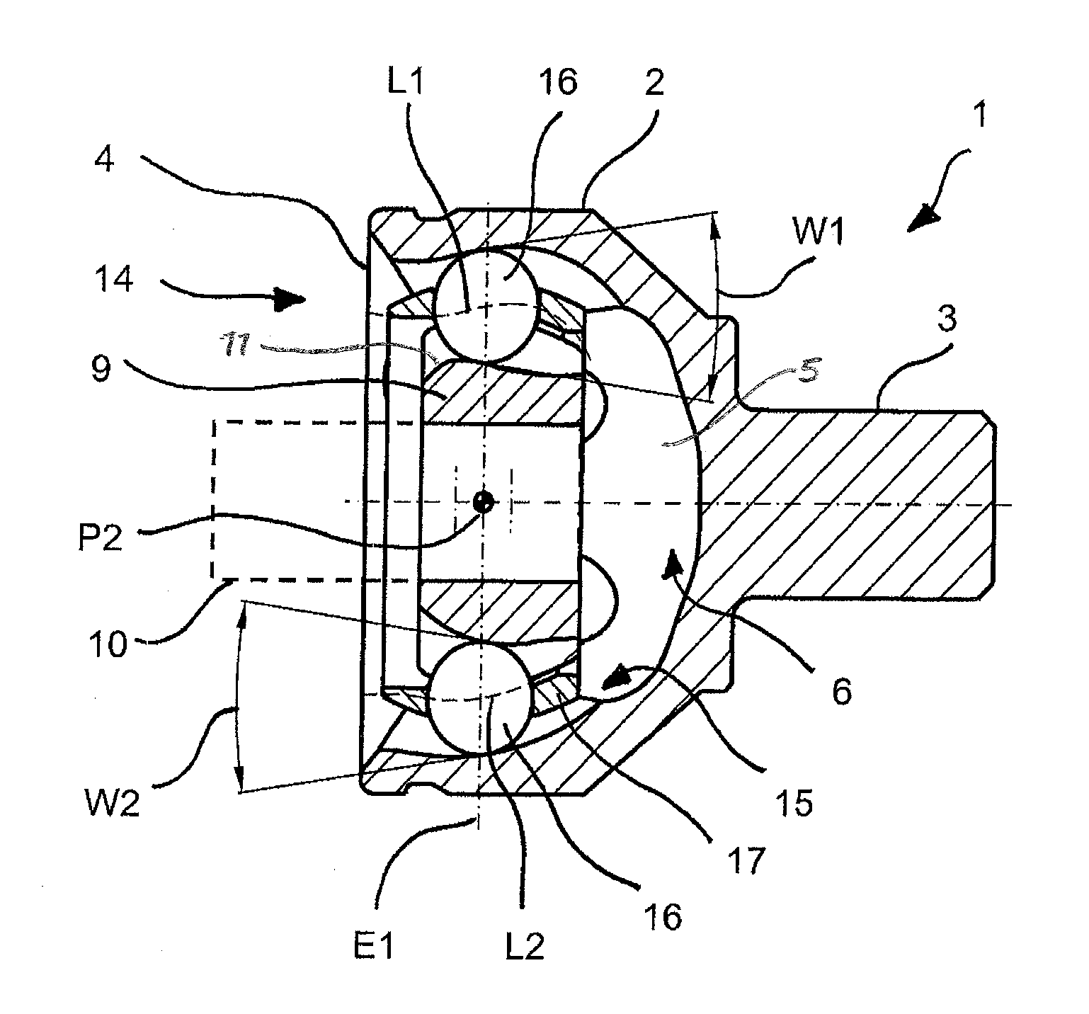
[0056]FIG. 1 illustrates the principle structure of an exemplary constant velocity ball joint 1. The constant velocity ball join includes an outer joint part 2 and balls 16, a cage 17 and an inner joint part 9, which may be connected to a shaft 10. The torque is transmitted by balls 16 from the inner ball tracks to the outer ball tracks.

[0057]Outer joint part 2 includes a conn...


PUM


Abstract

An exemplary constant velocity ball joint in the nature of a counter track joint, includes first and second track pairs that form an opposite opening angle (W1, W2), wherein the first track pairs are provided with a track inflection point (P1) and the second track pairs each form a second track centerline (L2) that has a path other than a singular circular path in a section between the central joint plane (E1) and the connection side.

Description

CROSS-REFERENCE TO RELATED APPLICATION[0001]This application is a National Stage application that claims the benefit of International Application No. PCT / EP2006 / 009893, filed Oct. 13, 2006, which is hereby incorporated by reference in its entirety.BACKGROUND AND SUMMARY[0002]The present device relates to a counter track joint. The joint may include an outer joint part, an inner joint part, a plurality of torque transmitting balls and a cage. Different designs of track pairs may be formed with the outer joint part and inner joint part, which form opening angles on opposite sides of the constant velocity ball joint.[0003]Counter track joints of this type are disclosed generally in DE 102 20 711 A1l , which describes joints with six balls or eight balls. Here the type of ball tracks corresponds to a type known as a Rzeppa joint (RF joints) and from the undercut-free joints (UF joints). This means that the centerlines of the ball tracks consist of uniform radii (RF joint) or that they a...

Claims


Application Information

Patent Timeline
Patent Type & Authority Applications(United States)
IPC IPC(8): F16D3/223F16D3/2233
CPCF16D3/2233F16D2003/22303F16D2003/22306
Inventor WECKERLING, THOMASKHOSHOEI, NADERAMENABAR, RAMONURETA, XABIERCUBERT, JOSEGUTIERREZ, INAKI
Owner GKN DRIVELINE INT GMBH
Why Eureka
Try Eureka