Tripode joint for increased articulation angles

a technology of articulation angle and tripode, which is applied in the direction of yielding couplings, couplings, rotary machine parts, etc., can solve the problems of generating much higher production costs or less advantageous in respect of nvh, and achieve the effect of large operating articulation angles

Inactive Publication Date: 2005-10-25
GKN DRIVELINE DEUTSCHLAND GMBH
View PDF4 Cites 11 Cited by
  • Summary
  • Abstract
  • Description
  • Claims
  • Application Information

AI Technical Summary

Benefits of technology

[0003]The present invention provides AAR tripode joints which are suitable for larger operational articulation angles. According to a solution in accordance with the invention, the roller carriers, on their outer faces, comprise stop collars which delimit the needle contact face, and which are held with an axial displacement clearance in the direction of the roller axes between axial securing members in such a way that they are secured against being lost relative to the rollers. The roller carriers, on their inner faces, with reference to the first longitudinal axis, at least on the radial inside end, comprise cylindrical projections which, with reference to the roller axes, increase the axial length of the arm contact faces beyond the extension of the needle contact faces.
[0005]In an advantageous embodiment, the axial securing members each comprise at least one securing ring which engages an inner annular groove in the rollers. The rollers, in the form of second axial securing members, can comprise an integrally formed on collar which, in respect of function, corresponds to a securing ring. This design ensures an easy axial assembly of the rollers, bearing needles and roller carriers. According to a another embodiment, the axial securing members each comprise two identical securing rings which engage two identical inner annular grooves in each roller and, between them, enclose the roller carrier with the inventive displacement clearance in accordance with the invention in such a way that it cannot get lost.
[0007]According to another embodiment, on the roller carriers, with reference to the first longitudinal axis, on their radial outside end, are contacted by arm contact faces and needle contact faces in such a way these are flush with the roller carriers. In this way, roller carrier weight can be saved.
[0008]According to a further embodiment, the roller carriers, with reference to the first longitudinal axis, on their radial outside end, comprise cylindrical projections which, with reference to the roller axes, increase the axial length of the arm contact faces beyond the extension of the needle contact faces. In this embodiment, the roller carrier can be designed to be symmetrical in order to simplify assembly.

Problems solved by technology

Such solutions are either less advantageous in respect of their NVH (noise, vibration) harshness) behavior (DO plunging joints) or generate much higher production costs (fixed ball joints with additional plunging units).

Method used


Image

  • Tripode joint for increased articulation angles
  • Tripode joint for increased articulation angles
  • Tripode joint for increased articulation angles

Examples


Embodiment Construction

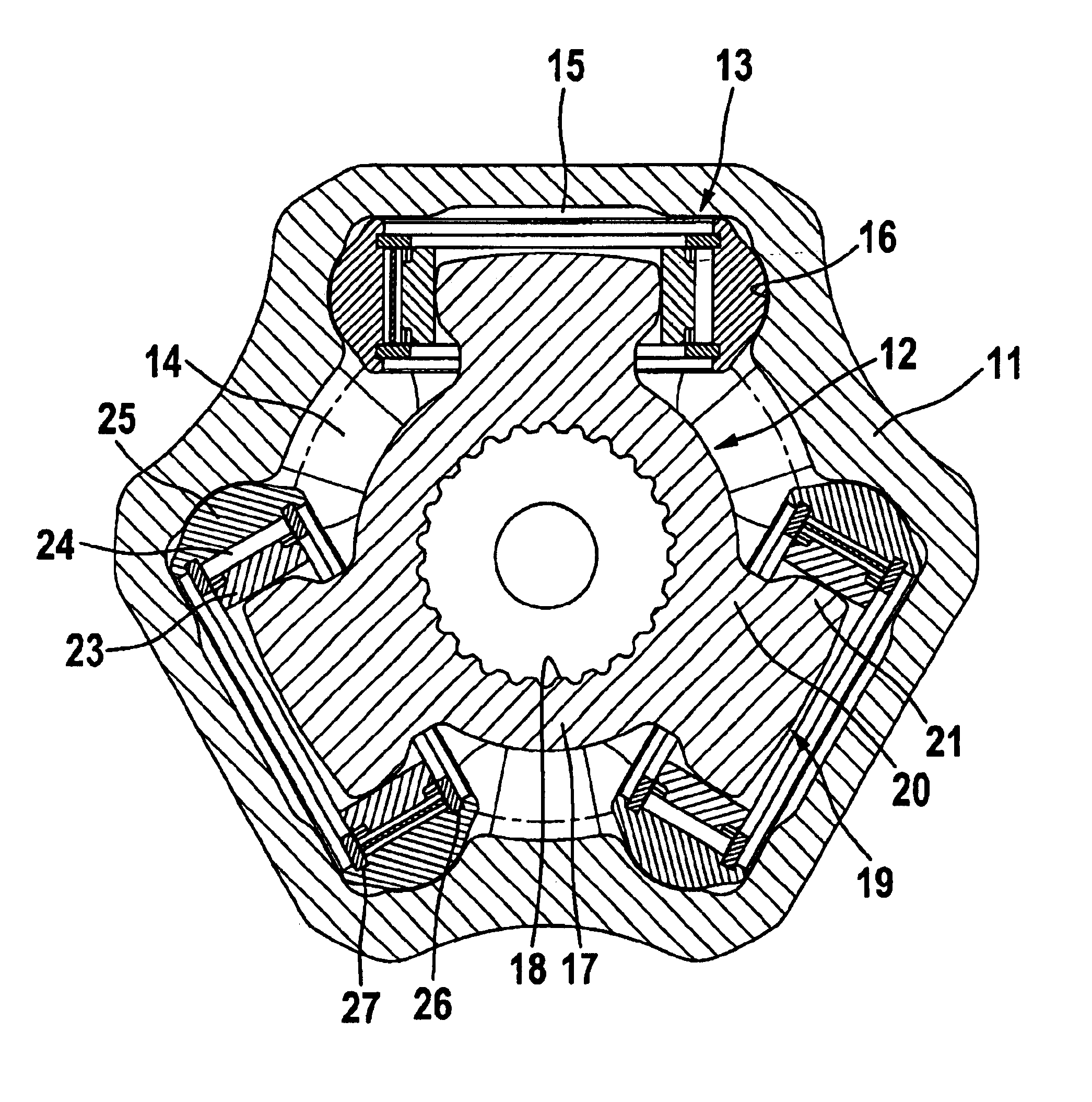
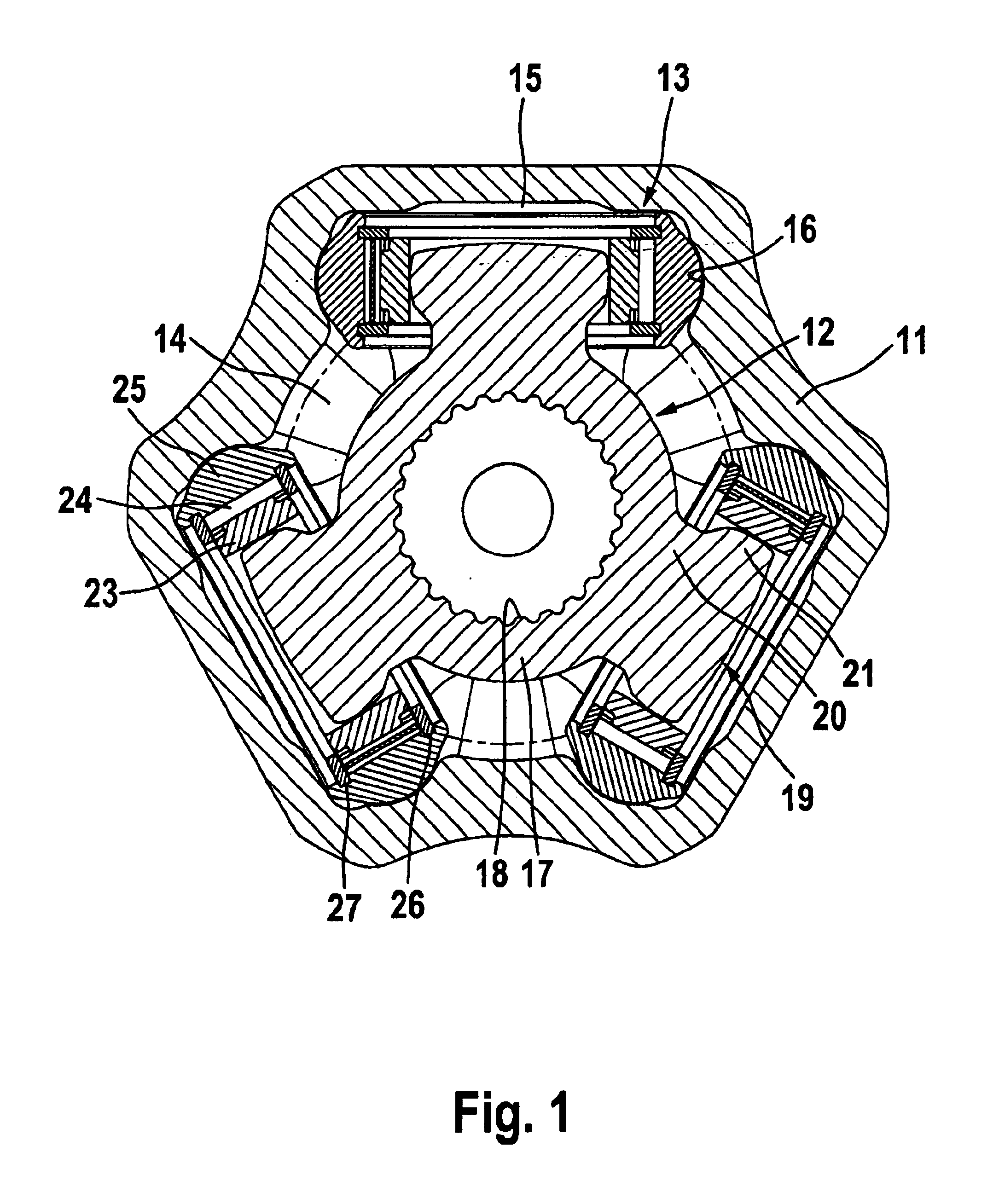
[0017]FIGS. 1 shows an inventive tripode joint in a cross-sectional view in which it is possible to identify an outer joint part 11, an inner joint part referred to as a so-called tripode star 12, as well as three roller assemblies 13. The outer joint part 11 also referred to as joint tulip is provided with an inner recess 14 and three uniformly circumferentially distributed recesses or widened regions 15 which are each occupied by one of the roller assemblies 13. The recesses 15 form pairs of circumferentially opposed fillet-shaped tracks 16. The tripode star 12 comprises an annular hub member 17 provided with an inner recess 18 for inserting a shaft. At the hub 17 there are arranged three uniformly circumferentially distributed tripode arms 19 which each comprise a reduced arm neck 20 and a arm head 21 provided with a partially spherical guiding face 22. The roller assemblies 13 each comprise a substantially hollow-cylindrical roller carrier 23, bearing needles 24 and externally s...


PUM


Abstract

A tripode joint having an outer joint part (11) having three uniformly circumferentially distributed recesses (15) which forms pairs of circumferentially opposed tracks (16) for receiving a roller assembly (13). Each roller assembly (13) is carried on an arm (19) of a tripode star (12). Each arm head has a spherical surface portion. Each roller assembly (13) includes an annular roller carrier (23, 123), bearing needles (24) rotating on the roller carrier (23, 123), and rollers (25) which are rotatably supported on the bearing needles (24). The roller carriers (23, 123) include stop collars which delimit the needle contact face, and which are held with an axial displacement clearance in the direction of the roller axes between axial securing members (26, 27) in such a way that they are secured against being lost relative to the rollers (25).

Description

TECHNICAL FIELD[0001]The invention relates to a tripode joint having an outer joint part with a first longitudinal axis and an inner recess and three uniformly circumferentially distributed recesses which widen the inner recess and which form pairs of circumferentially opposed tracks. The joint also includes a tripode star with a second longitudinal axis and a hub and three uniformly circumferentially distributed tripode arms which are arranged radially at the hub. Each arm includes an arm head with a spherical surface portion, and an assembly comprising an annular roller carrier, bearing needles rotating on the roller carrier, and rollers which are rotatably supported on the bearing needles. The roller carriers, on their inner faces, each comprise a cylindrical arm contact face and, on their outer faces, a cylindrical needle contact face. Further, each of the arm heads holds a roller assembly and each of the roller assemblies is guided in one of the recesses. The roller carriers ar...

Claims


Application Information

Patent Timeline
Patent Type & Authority Patents(United States)
IPC IPC(8): F16D3/205F16D3/16
CPCF16D3/2055F16D2003/2023Y10S464/905F16D2003/2026
Inventor HOFMANN, NORBERT
Owner GKN DRIVELINE DEUTSCHLAND GMBH
Why Eureka
Try Eureka