Positioning system

a positioning system and tool technology, applied in the field of positioning systems, can solve the problems of increasing uncertainty, reducing the practicability of drilling, and inaccurate measurement of the inserting length of tubing strings, so as to reduce the friction and reduce the friction and thereby the effect of friction

Active Publication Date: 2018-06-07
COMITT WELL SOLUTIONS LLC
View PDF3 Cites 9 Cited by
  • Summary
  • Abstract
  • Description
  • Claims
  • Application Information

AI Technical Summary

Benefits of technology

[0022]The axial extension of the latch may vary along the wellbore. For example, the axial lengths of annular grooves in the casing members could increase in the downhole direction such that a protruding latching member with a certain axial extension would pass a number of markers before it enters the first groove with sufficient length. Alternatively, protruding markers could have decreasing lengths in the downhole direction to achieve the same effect.
[0023]Preferably, the latch comprises a roller ball engaging walls that are inclined with respect to a radial plane. The purpose is to reduce the effect of friction between a solid lug and the inclined wall, in particular those caused by a well fluid lubricating steel surfaces, as the lubrication would depend on the well fluid and possibly local temperature and pressure. Alternatively, the engaging lug may be coated with a suitable material such as PTFE to reduce the friction and thereby the effects of the friction.

Problems solved by technology

As a tubing string with a working tool may take slightly different paths through the wellbore each time it is used, measuring the inserted length of tubing string is inaccurate.
The uncertainty increases with distance from the surface, and may easily become impractically large some kilometers along the wellbore.
Similar problems are encountered during logging, e.g. using a wireline or slickline tool.
Thus, a casing-collar locator tends to be relatively expensive and precise or less expensive and less accurate, so there is a need for a more accurate and less expensive positioning tool.

Method used


Image

  • Positioning system
  • Positioning system
  • Positioning system

Examples


Embodiment Construction

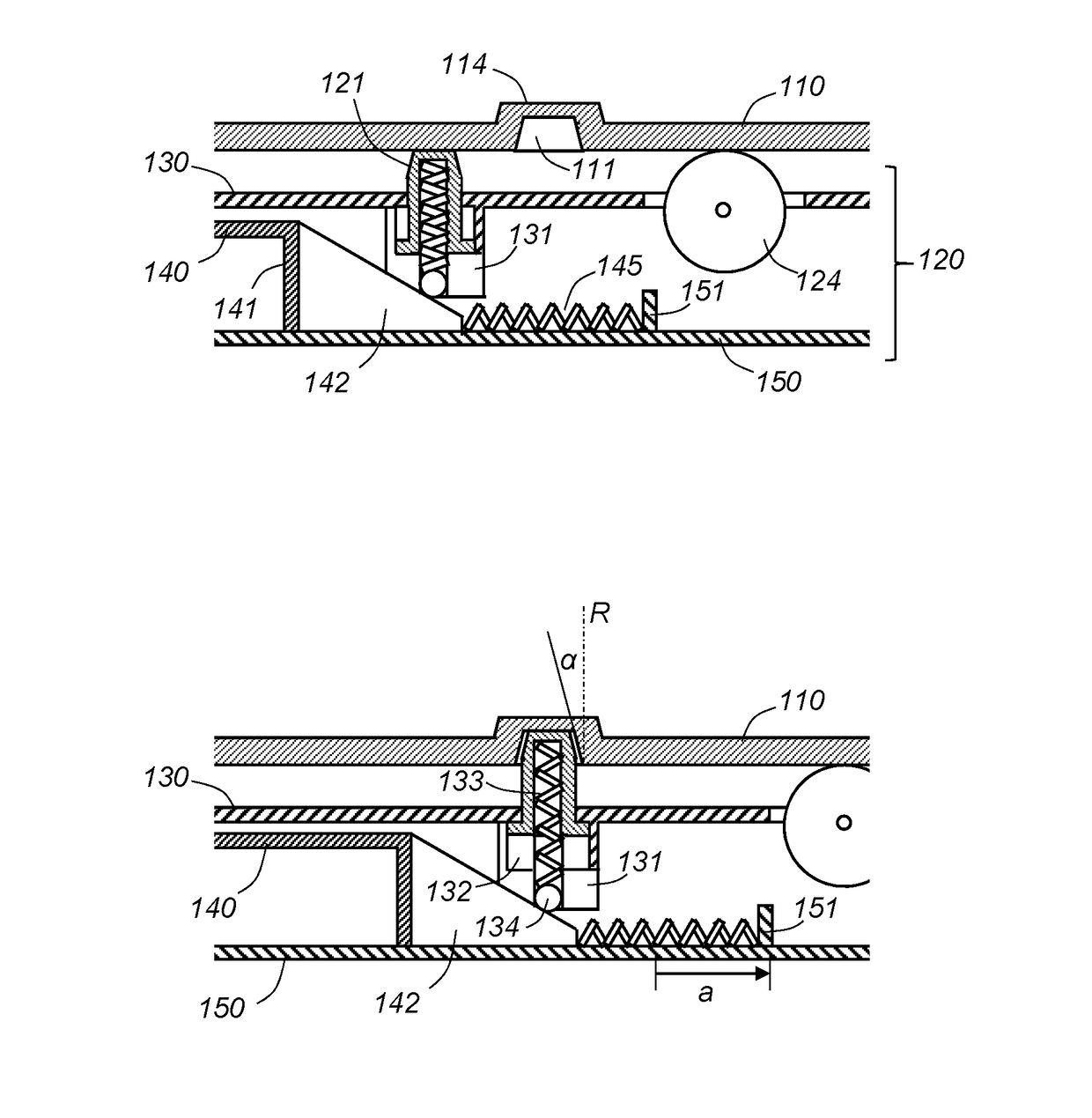
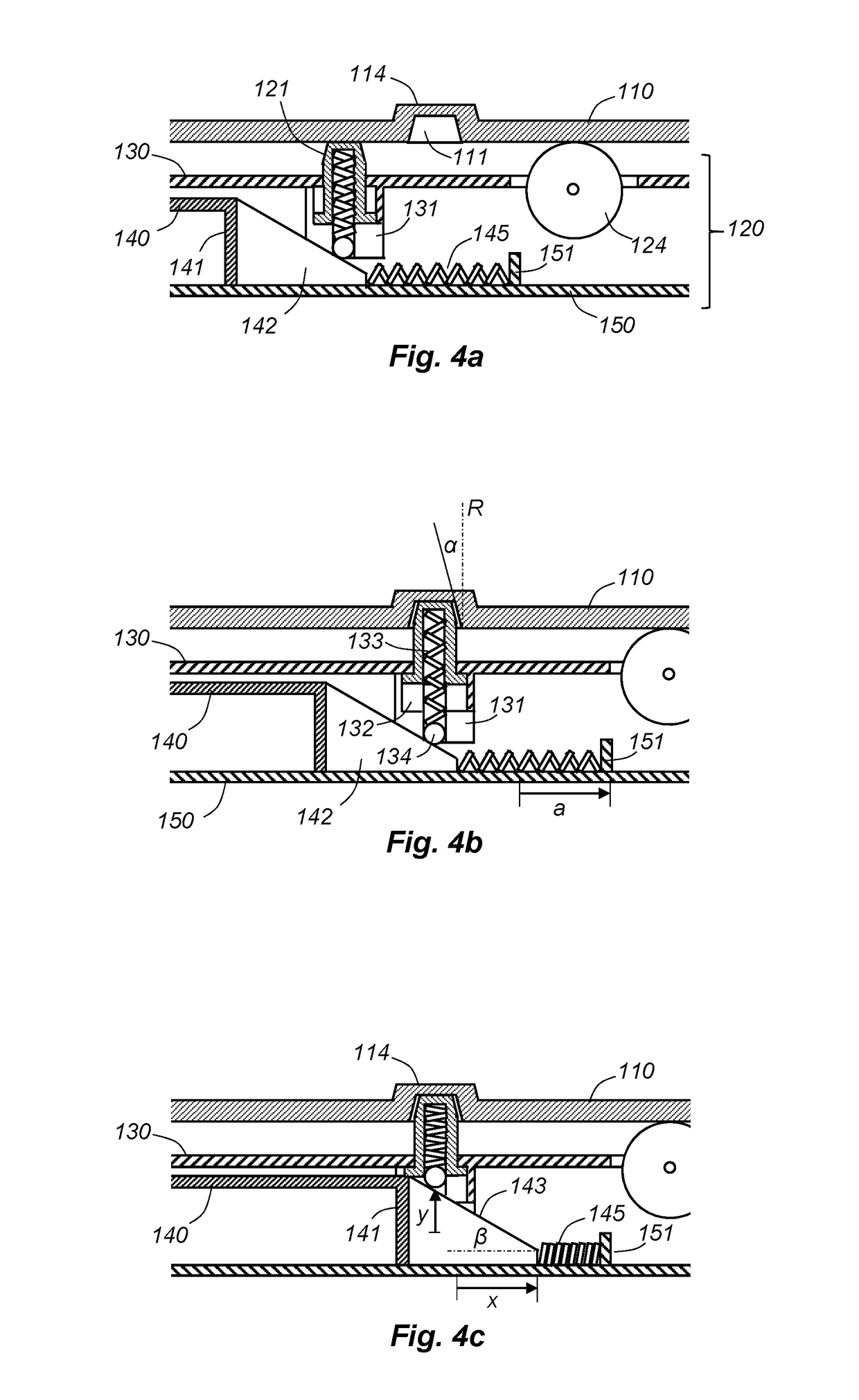
[0037]The drawings are schematic and not necessarily to scale. Numerous details known to the skilled person are omitted from the drawings and following description. Furthermore, in the claims, the terms “a”, “an” and “the” means “at least one” and “one” means exactly one, whereas terms such as “several” and “at least one” may be used in the following detailed description for ease of understanding.

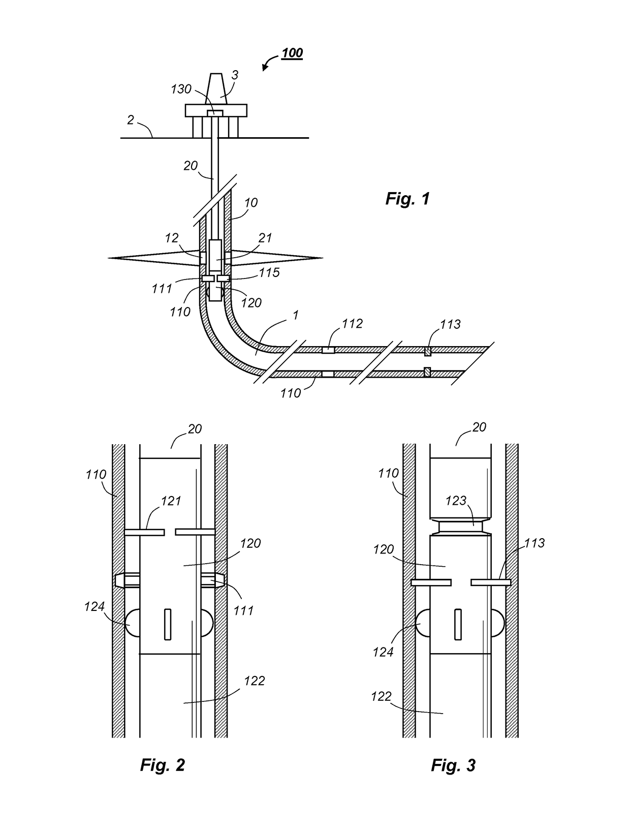
[0038]FIG. 1 illustrates a system 100 according to the invention. Reference numerals above 100 refer to components of the system, whereas reference numerals below 100 are provided to explain the context of the system 100 in use, and are not part of the invention as such.

[0039]More particularly, FIG. 1 depicts a wellbore 1 extending vertically and horizontally through a geological formation. The wellbore 1 may be located onshore or offshore, and the surface 2 may thus be a sea surface or dry land. The wellbore 1 is lined with a casing 10, which comprises casing joints with different outer di...


PUM


Abstract

A system (100) for positioning a working tool (21) in a wellbore (1). The positioning system (100) comprises a casing element (110) with a marker (111, 112, 113) provided on an inner surface, the marker (111, 112, 113) having a distinct diameter different from the inner diameter of the casing element (110). The system further comprises a positioning tool (120) with a latching element (121, 122) adapted to form a latch (115) with the marker (111, 112, 113), and a force detector (130) adapted to detect an axial latching force (FL) applied to a tubing string (20) from the latch (115) when the casing element (110) is located within the wellbore (1) and the force detector (130) is located at a surface (2) outside the wellbore (1).

Description

BACKGROUNDField of the Invention[0001]The present application concerns a system for positioning a tool in a wellbore.Prior and Related Art[0002]The present invention may be used in wells in general, i.e. regardless of related field of technology. For example, the invention may be used in a well for exploration, production or injection in the oil and gas industry, similar wells in geothermal applications or a well for producing ground water. The terminology varies slightly between the fields of technology, and sometimes within each field. Thus, the next few paragraphs describe well known procedures to precisely define terms that are central to the present invention.[0003]Creating a well starts by drilling a borehole through a geological formation, e.g. soil, sand, clay and rock of various kinds. The drilling may involve rotating a drill string with a drill bit on a downhole end while a drilling fluid is pumped down within the central bore of the drill string. The drill bit cuts mater...

Claims


Application Information

Patent Timeline
Patent Type & Authority Applications(United States)
IPC IPC(8): E21B23/02
CPCE21B23/02E21B17/105E21B17/1057E21B47/0905E21B47/09E21B23/01E21B47/092
Inventor CLEVEN, PETER KRIS
Owner COMITT WELL SOLUTIONS LLC
Why Eureka
Try Eureka