Guide bar fastening device for chain saw

Active Publication Date: 2014-10-02
MAKITA CORP
View PDF21 Cites 9 Cited by
  • Summary
  • Abstract
  • Description
  • Claims
  • Application Information

AI Technical Summary

Benefits of technology

[0007]The present invention is provided in order to solve the problems in the conventional guide bar fastening device, and thus, an object of the present invention is to provide a guide bar fast

Problems solved by technology

However, in such a guide bar fastening mechanism, a length of the lever is short because the length is limited by the size of the rotating knob, and accordingly, it might b

Method used


Image

  • Guide bar fastening device for chain saw
  • Guide bar fastening device for chain saw
  • Guide bar fastening device for chain saw

Examples


Embodiment Construction

[0025]Hereunder, an embodiment of the present invention will be described with reference to the accompanying drawings.

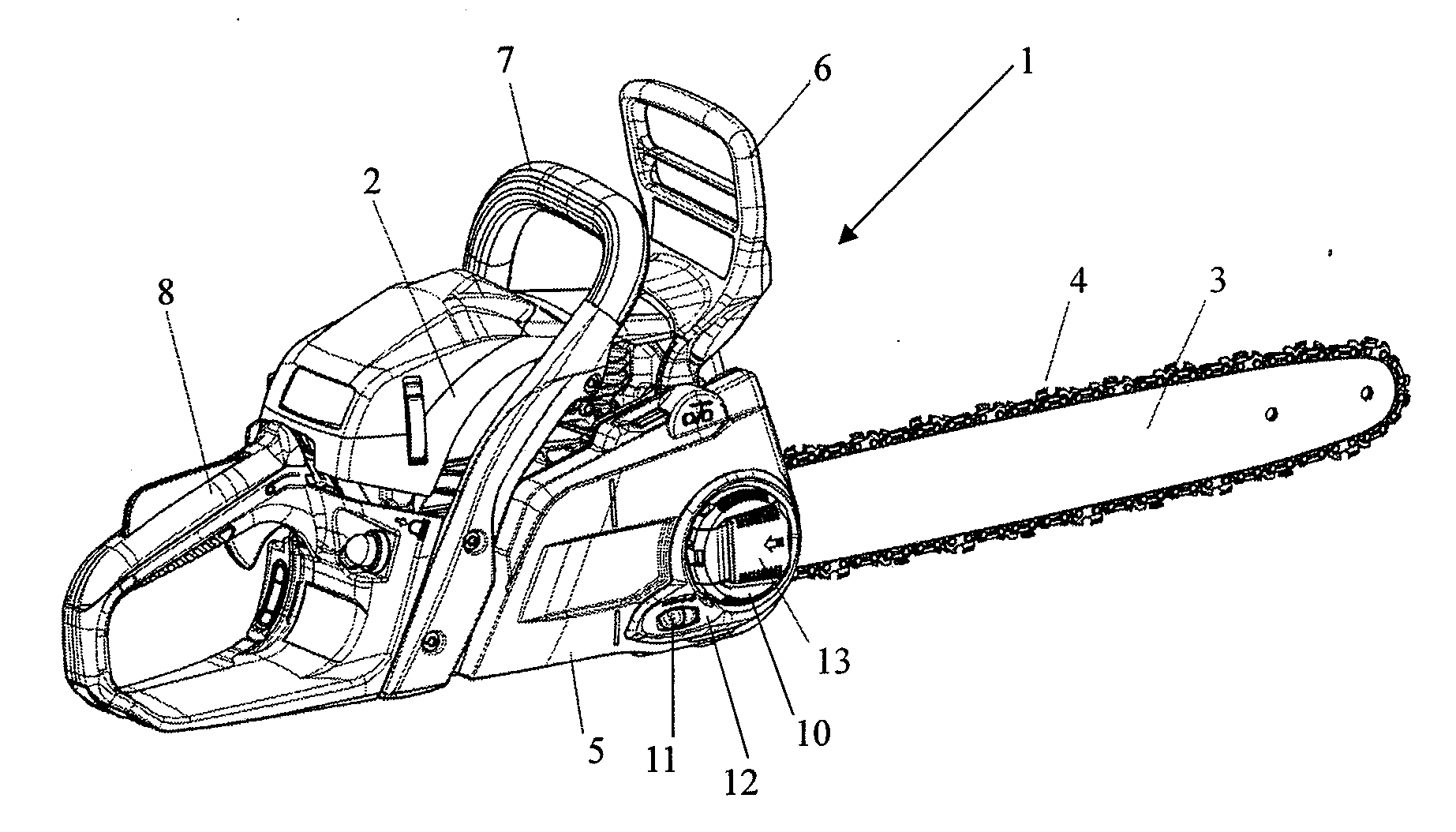
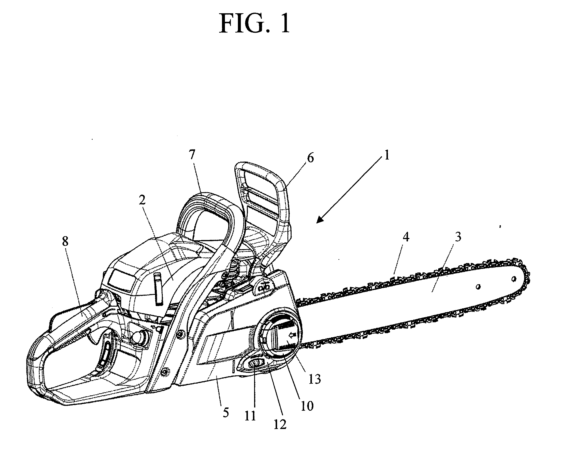
[0026]FIG. 1 illustrates an overall configuration of a chain saw according to an embodiment of the present invention, and FIGS. 2 to 6 illustrate a configuration of each component.

[0027]In a chain saw 1, a guide bar 3 extending frontward is attached to a chain saw body (hereinbelow, referred to as “body”) 2. On a peripheral portion of the guide bar 3, a saw chain 4 is supported.

[0028]The saw chain 4 engages with a sprocket (not illustrated) that is driven to be rotated by a motor, such as an engine or an electric motor, in the body 2, to be rotated around the sprocket and the peripheral portion of the guide bar 3, one end portion of which adjoins the sprocket.

[0029]An area around the sprocket, a part of the guide bar 3, and the like, is covered by a chain cover 5. The chain cover 5 is attached to the body 2.

[0030]At the front part of the body 2, a front guard 6 that ...


PUM

PropertyMeasurementUnit
Lengthaaaaaaaaaa
Forceaaaaaaaaaa
Angleaaaaaaaaaa

Abstract

To provide an operation lever including a first lever that has a base end portion swingably supported to a peripheral portion of a nut member for fastening a guide bar in a chain saw, and a second lever that is engaged with the first lever in a manner slidable in an axial direction. The operation lever can be placed in a receiving portion of the nut member with an axial length thereof shortened, and can be manipulated to rotate the nut member by being gripped on an outer end portion of the second lever in a state in which the operation lever is lifted out from the receiving portion and the axial length is lengthened. Thus, a sufficient fastening force for the guide bar can be obtained, and operability can be improved.

Description

BACKGROUND OF THE INVENTION[0001]1. Field of the Invention[0002]The present invention relates to a device, for use in a chain saw, the device fastens a guide bar that supports a saw chain on a peripheral portion thereof to a chain saw body.[0003]2. Description of Related Art[0004]A chain saw is configured to secure a guide bar, which supports a saw chain on a peripheral portion of the guide bar, to a chain saw body with a bolt member and a nut.[0005]Japanese Laid-open Patent Application Publication No. 2006-103301 discloses a guide bar fastening device, in which a guide bar is manually fastened (and unfastened) by rotating a semicircular lever, that is supported to a semicircular rotating knob in a diametral direction thereof, the knob being integrally secured on a nut fastening the guide bar, to thereby rotate the nut.[0006]However, in such a guide bar fastening mechanism, a length of the lever is short because the length is limited by the size of the rotating knob, and accordingly...

Claims


Application Information

Patent Timeline
IPC IPC(8): B27B17/02
CPCB27B17/02B27B17/14
Inventor TAKAYANAGI, YOSHIAKISUGIYAMA, MASASHI
Owner MAKITA CORP
Why Eureka
Try Eureka