Two-cycle combustion engine

Active Publication Date: 2007-05-31
KAWASAKI MOTORS LTD
View PDF1 Cites 10 Cited by
  • Summary
  • Abstract
  • Description
  • Claims
  • Application Information

AI Technical Summary

Benefits of technology

[0010] In one preferred embodiment of the present invention, the cylinder block may be formed with threaded holes and the crankcase may also be formed with a mating fastening-member insertion hole, which is aligned with the threaded holes in the cylinder block when the latter is mounted atop the crankcase. In such case, the fastening member may be a fastening bolt that is passed through the respective insertion hole to be threaded into the threaded hole to connect the cylinder block and the crankcase together. This is particularly advantageous in that the connecting structure can be simplified since the cylinder block and the crankcase can be firmly connected together by means of the fastening bolts.
[0011] In another preferred embodiment of the present invention, the first crank casing may be formed with a recess. The recess defines a bolt access passage through which the corresponding fastening bolt can be fastened to or removed from the cylinder block. Formation of those recesses allows the use of the fastening bolts of a relatively short length to advantageously accomplish a firm connection between the crankcase and the cylinder block.
[0012] In a further preferred embodiment of the present invention, the second crank casing may be formed with a fan covering portion covering a fan of the engine and having an air suction opening for the fan defined therein, in which case the air suction opening forms a bolt access passage through which the corresponding fastening bolt can be fastened to or removed from the cylinder block. This is particularly advantageous in that since the fastening bolts can be passed or removed by the fastening tool passed through the air suction openings, the fastening bolts of a relatively short length can be used.
[0013] According to the present invention, the cylinder block preferably has an air intake passage defined therein for introducing air from one side of the cylinder block to a scavenging passage of the engine. In this case, the air intake passage is positioned above the fastening members and open at the one side of the cylinder block. According to this structural feature, this air intake passage need not be so shaped as to be curved to bypass respective points of connection defined by the fastening members, but is so shaped as to linearly communicate from the opening on the one side of the cylinder block to the s

Problems solved by technology

For this reason, the use of this known connecting structure has been found involving a problem associated with reduction in cooling performance of the cylinder block as the total surface area of the cooling fins is reduced in the presence of the series-aligned tool insertion holes in the cylinder block.
Also, the presence of those tool insertion holes necessarily causes the cooling fins to represent rugged shapes particularly in a direction circumferentially of the cylinder block and also causes the thermal tr

Method used


Image

  • Two-cycle combustion engine
  • Two-cycle combustion engine
  • Two-cycle combustion engine

Examples


Example

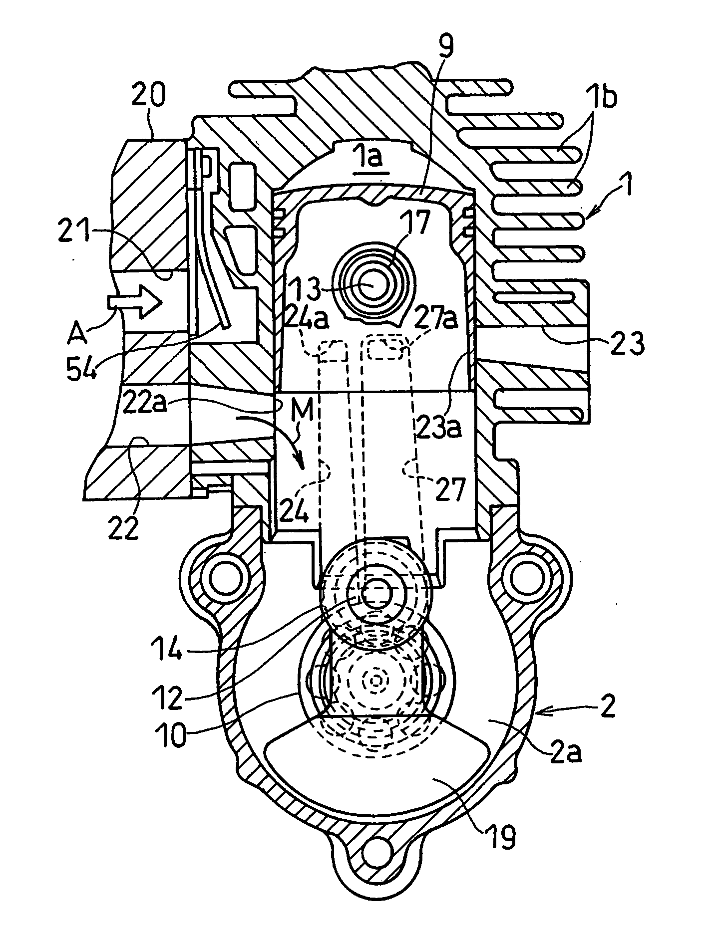
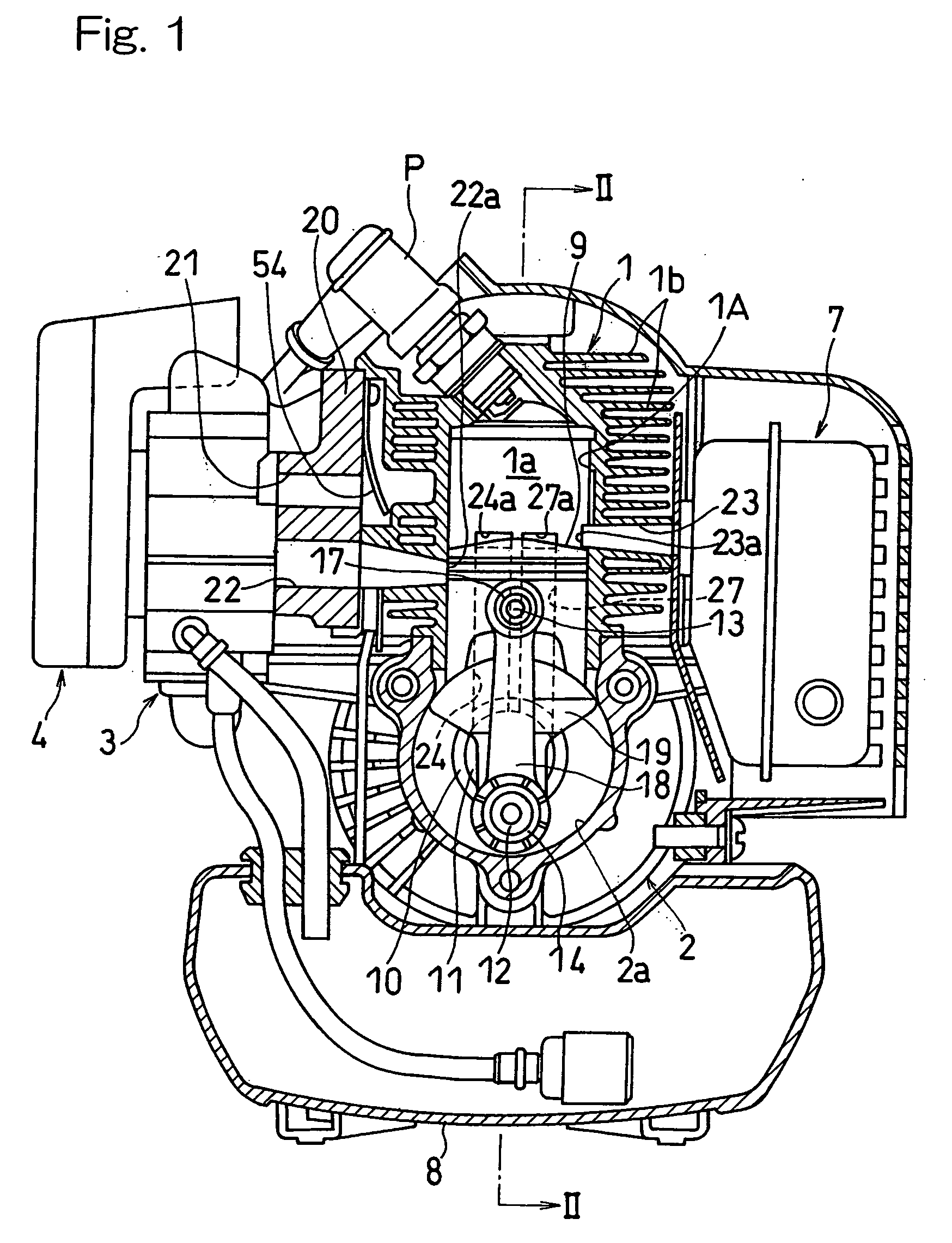
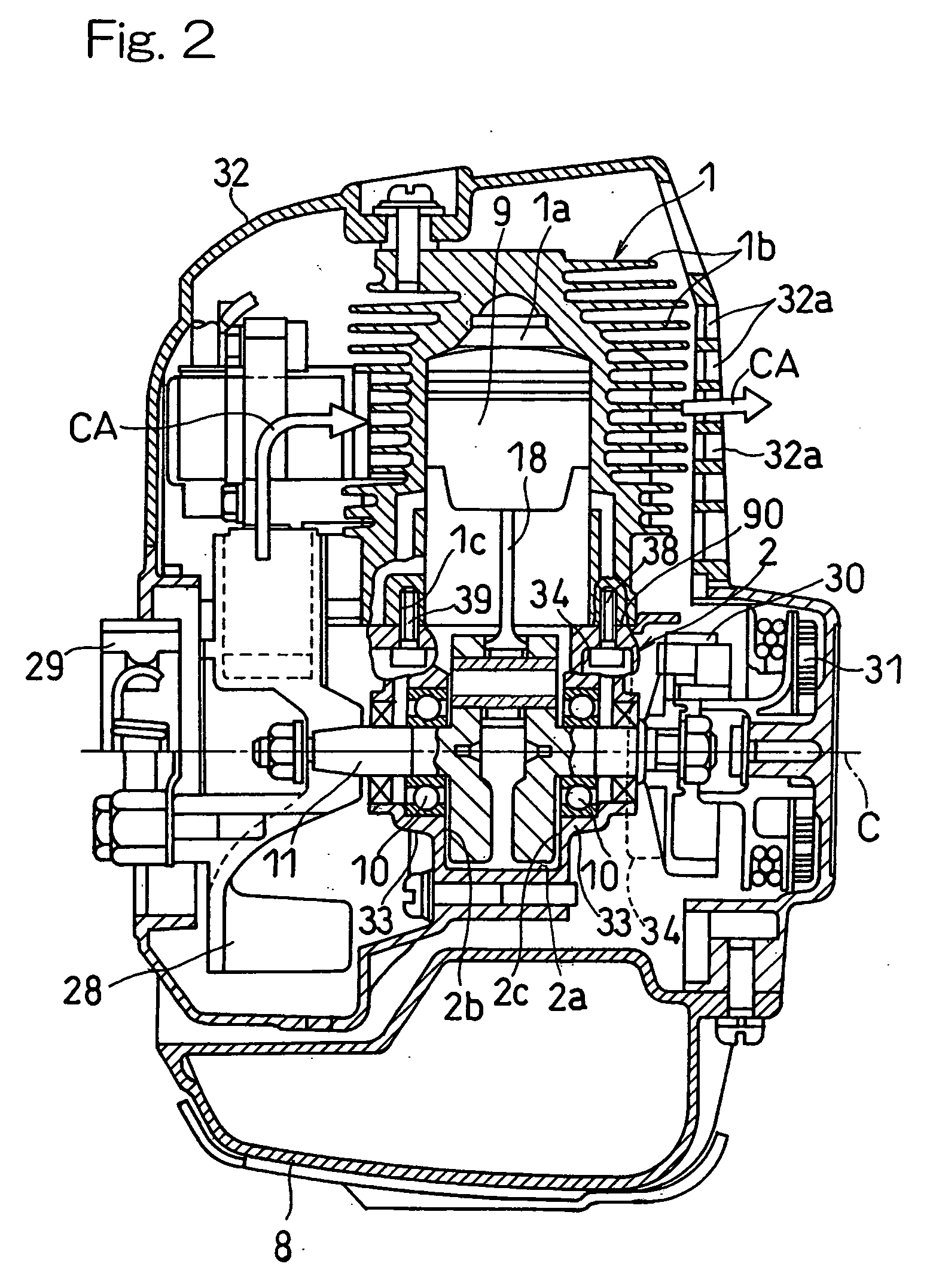
[0036] Hereinafter, the present invention will be described in connection with preferred embodiments thereof with reference to the accompanying drawings. In particular, FIG. 1 illustrates a traverse cross-sectional view of the two cycle combustion engine according to a first preferred embodiment of the present invention as viewed in a direction transverse to the axis about which a crankshaft rotates, and FIG. 2 shows a longitudinal cross-section taken along the line II-II shown in FIG. 1. In this embodiment, a small-size two-cycle internal combustion engine utilizable in a brush cutter is illustrated.

[0037] Referring now to FIG. 1, the two cycle combustion engine shown therein includes a cylinder block 1 having a combustion chamber la defined therein, and a crankcase 2 having a crank chamber 2a defined therein, in which the cylinder block 1 is connected with an upper portion of the crankcase 2. Each of the cylinder block 1 and the crankcase 2 is made of a metallic material such as,...


PUM


Abstract

To provide a two cycle combustion engine utilizing a connecting structure of a shape that can be formed inexpensively with a simple process to enable the efficiency of cooling of the cylinder block to be maintained at a high level and, also, that can firmly connect the cylinder block with the crankcase with fastening forces exerted by the fastening bolts, the two cycle combustion engine includes a crankcase 2 including first and second crank casings 2A and 2B that are split in a direction conforming to a crank axis C for operatively supporting a crankshaft 11, and a cylinder block 1 having a cylinder bore 1a defined therein and fixedly mounted atop the crankcase 2 by means of a plurality of fastening members 38 and 39 fitted in a direction upwardly from a crankcase-side.

Description

BACKGROUND OF THE INVENTION [0001] 1. Field of the Invention [0002] The present invention relates generally to a small-size two cycle combustion engine of a kind used as a drive source for a work machine or equipment such as, for example, a brush cutter. More specifically, the present invention relates to the two cycle combustion engine of a structure, in which a cylinder block is connectedly mounted on a crankcase that is divided into two crank casings in a direction axially of a crankshaft accommodated in the crankcase. [0003] 2. Description of the Prior Art [0004] In the small-size combustion engine of a type utilizing the crankcase that is divided into two crank casings in a direction axially of the crankshaft, a connecting structure has been hitherto generally employed, in which fastening bolts inserted from above into corresponding insertion holes defined in a cylinder block flange at a lower portion of the cylinder block are threadingly engaged in associated internally thread...

Claims


Application Information

Patent Timeline
IPC IPC(8): F02B75/22
CPCF02B2075/025F02F7/0004F02F7/0036F02F7/0082
Inventor YUASA, TSUNEYOSHIYOSHIMIZU, ISAOKOBAYASHI, MASANORI
Owner KAWASAKI MOTORS LTD
Why Eureka
Try Eureka