Steering apparatus for vehicle

Active Publication Date: 2007-02-06
JTEKT CORP
View PDF19 Cites 5 Cited by
  • Summary
  • Abstract
  • Description
  • Claims
  • Application Information

AI Technical Summary

Benefits of technology

[0011]The present invention has been made with the aim of solving the above problems, and it is an object of the present invention to provide a steering apparatus for a vehicle, capable of simplifying the structure of the connection section of divided housings to store a nut member of a screw mechanism for converting rotation of a steering assist motor or a steering motor into movement of a steering shaft in an axial direction, and preventing deterioration in steering feeling due to the influence of thrust loads applied to the nut member.
[0013]In the first aspect, the nut member rotated by power transmission from a steering assist motor or a steering motor is supported by the thrust bearing fitted and fixed in the first housing having integrally formed fixing means for fastening to a vehicle body, thrust loads applied in both directions to the nut member with the conversion of rotation into movement of the steering shaft in an axial direction are carried by the first housing through the thrust bearing, the structure of the connection section of the first housing and second housing is simplified, and the housing is fixed in a stable manner to prevent deterioration in steering feeling.
[0017]In the third aspect, the mesh state of the gear transmission means can be readily adjusted by moving the transmission housing in a radial direction within the range of loose fitting clearance between the transmission housing and the first housing or the second housing.

Problems solved by technology

Therefore, great connection strength is required for the connection section of the first and second housings, and it is necessary to increase the thickness of connection flanges and the size and number of bolts for tightening the flanges, and thus this structure suffers from the drawbacks that the freedom of design is decreased and the weight of the product is increased.
However, when such a fixing structure is adopted, the fixation of the second housing comprising fixing means in a separate member becomes unstable due to the function of thrust forces repeatedly applied from the nut member in the inside, and this instability may influence steering performed by the movement of the sheering shaft and deteriorate steering feeling.

Method used


Image

  • Steering apparatus for vehicle
  • Steering apparatus for vehicle
  • Steering apparatus for vehicle

Examples


Embodiment Construction

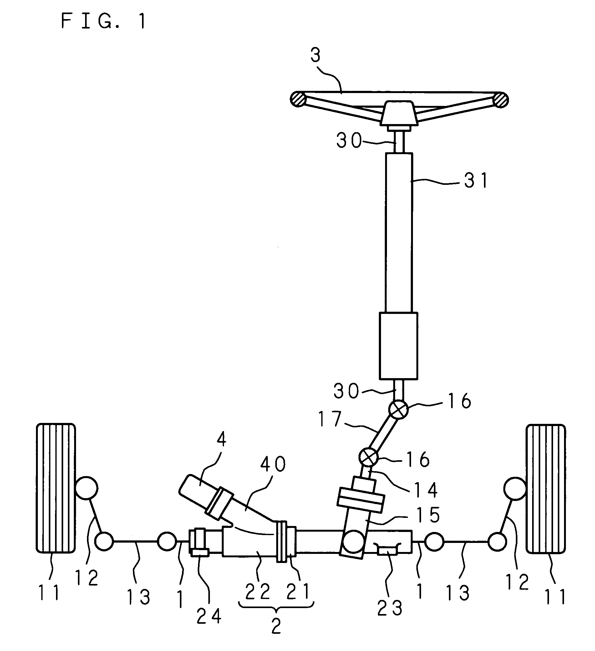
[0024]The following description will explain the present invention in detail, based on the drawings illustrating an embodiment thereof. FIG. 1 is a schematic diagram showing the entire structure of a steering apparatus for a vehicle according to the present invention. The steering apparatus for a vehicle shown in FIG. 1 is constructed as a rack / pinion type electric power steering apparatus comprising a rack / pinion type steering mechanism which operates according to turning of a steering wheel 3 as a steering member, and a motor 4 which is provided in the steering mechanism and driven to assist steering.

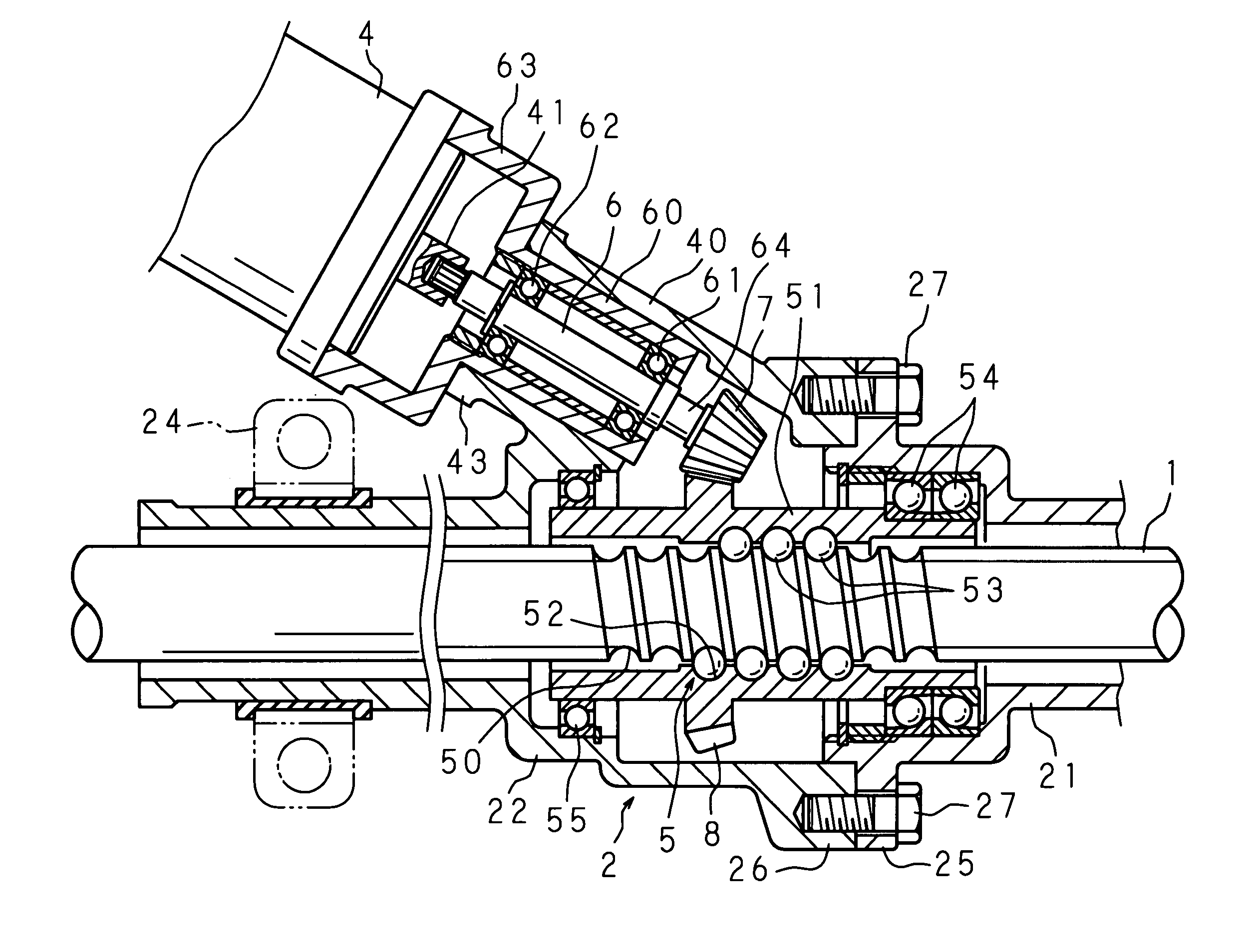
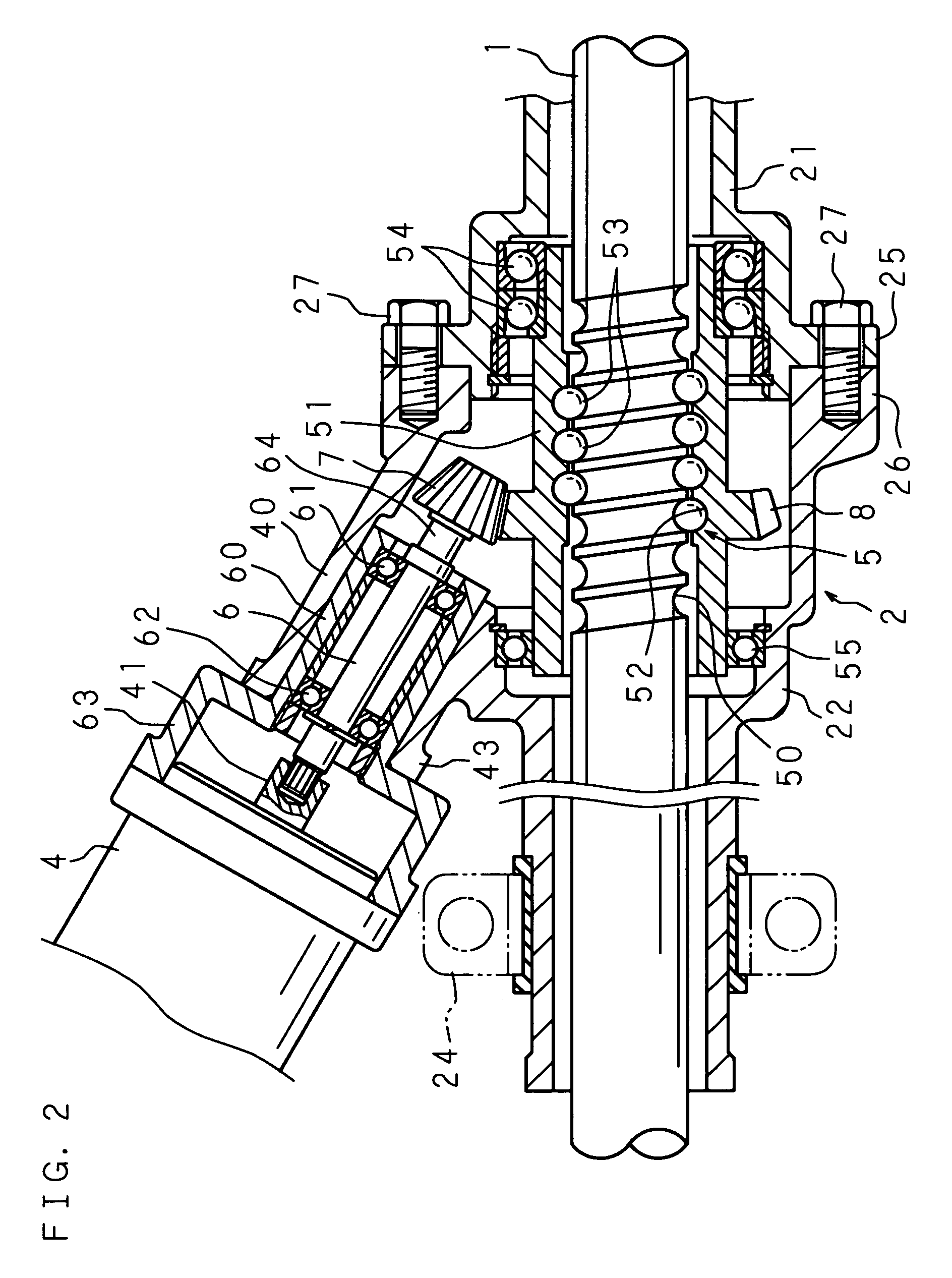
[0025]The steering mechanism comprises a cylindrical rack housing 2 extending in the left-right direction of a vehicle body (not shown), and a steering shaft (rack shaft) 1 supported in the rack housing 2 so that it can freely move in an axial direction. The rack housing 2 comprises a first housing 21 and a second housing 22 which are connected coaxially. For the first and second hous...


PUM


Abstract

A nut member which is rotated by power transmission from a motor in a rack housing is supported by a thrust bearing fitted and fixed in a first housing having an integrally formed fixing section for fastening to a vehicle body so that the nut member cannot move in both directions along an axial direction. Thrust loads applied in both directions to the nut member with the conversion of rotation into movement of a steering shaft in an axial direction are carried by the first housing through the thrust bearing. The structure of the connection section of the first housing and second housing is simplified, and the housing is fixed in a stable manner to prevent deterioration in steering feeling.

Description

CROSS-REFERENCE TO RELATED APPLICATIONS[0001]This application claims priority under 35 U.S.C. § 119 from Japanese Patent Application No. 2003-113416, filed on Apr. 17, 2003.BACKGROUND OF THE INVENTION[0002]The present invention relates to a steering apparatus for a vehicle, which is constructed to perform steering by transmitting rotation of a motor driven according to an operation of a steering member, such as a steering wheel, to a steering shaft in a steering mechanism and moving the steering shaft in the axial direction.[0003]A vehicle is steered by transmitting an operation of a steering member executed by a driver (in general, turning of a steering wheel) to a steering shaft in a steering mechanism (for example, a rack shaft in a rack / pinion type steering apparatus) and pushing and pulling vehicle wheels for steering (in general, the left and right front wheels) by the movement of the steering shaft in the axial direction to turn the wheels.[0004]As a steering apparatus for a ...

Claims


Application Information

Patent Timeline
IPC IPC(8): B62D5/04
CPCB62D5/0448B62D5/0421
Inventor NAGAMATSU, KAZUAKINAKAMURA, KENSAKUMURAKAMI, TETSUYASARUWATARI, TAKEHIROYAMANAKA, KOUSUKE
Owner JTEKT CORP
Why Eureka
Try Eureka