
Clamping device with precision measurement function for gear ring production and machining

A technology of precision measurement and clamping device, applied in workpiece clamping device, measurement device, mechanical measurement device, etc., can solve the problems of poor clamping accuracy, difficult ring gear support, and inability to move well in the measurement part. , to achieve the effect of convenient operation and convenient storage

Pending Publication Date: 2021-07-09
WUXI LONGDI PRECISED FORGINGS
View PDF0 Cites 0 Cited by
  • Summary
  • Abstract
  • Description
  • Claims
  • Application Information

AI Technical Summary

Problems solved by technology

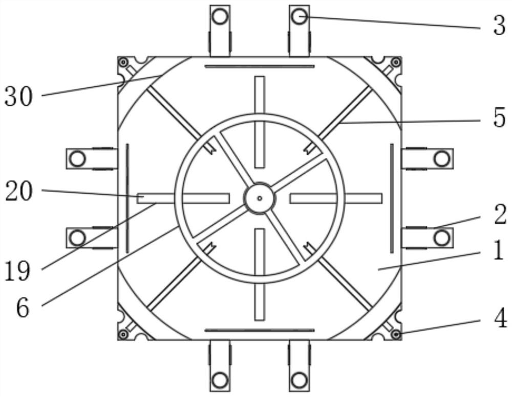
[0004] The object of the present invention is to provide a clamping device with precision measurement for the production and processing of ring gears, so as to solve the problems caused by the existing clamping device proposed in the above-mentioned background technology because the end part of the clamping device is not designed with a better precision measurement structure. The accuracy of the clamping process is poor, and the measurement part cannot be displaced well, resulting in inconvenient manipulation. At the same time, the support method of the clamping part is single, and it is difficult to use the support part to simply support the ring gear. As a result, the support placement is not convenient enough during processing, and the processing effect is not ideal.

Method used


Image

  • Clamping device with precision measurement function for gear ring production and machining
  • Clamping device with precision measurement function for gear ring production and machining
  • Clamping device with precision measurement function for gear ring production and machining

Examples


Embodiment Construction

[0026] The following will clearly and completely describe the technical solutions in the embodiments of the present invention with reference to the accompanying drawings in the embodiments of the present invention. Obviously, the described embodiments are only some, not all, embodiments of the present invention.

[0027] In the description of the present invention, unless otherwise stated, the meaning of "plurality" is two or more; the terms "upper", "lower", "left", "right", "inner", "outer" , "front end", "rear end", "head", "tail", etc. indicate the orientation or positional relationship based on the orientation or positional relationship shown in the drawings, and are only for the convenience of describing the present invention and simplifying the description, rather than Nothing indicating or implying that a referenced device or element must have a particular orientation, be constructed, and operate in a particular orientation should therefore not be construed as limiting ...


PUM


Abstract

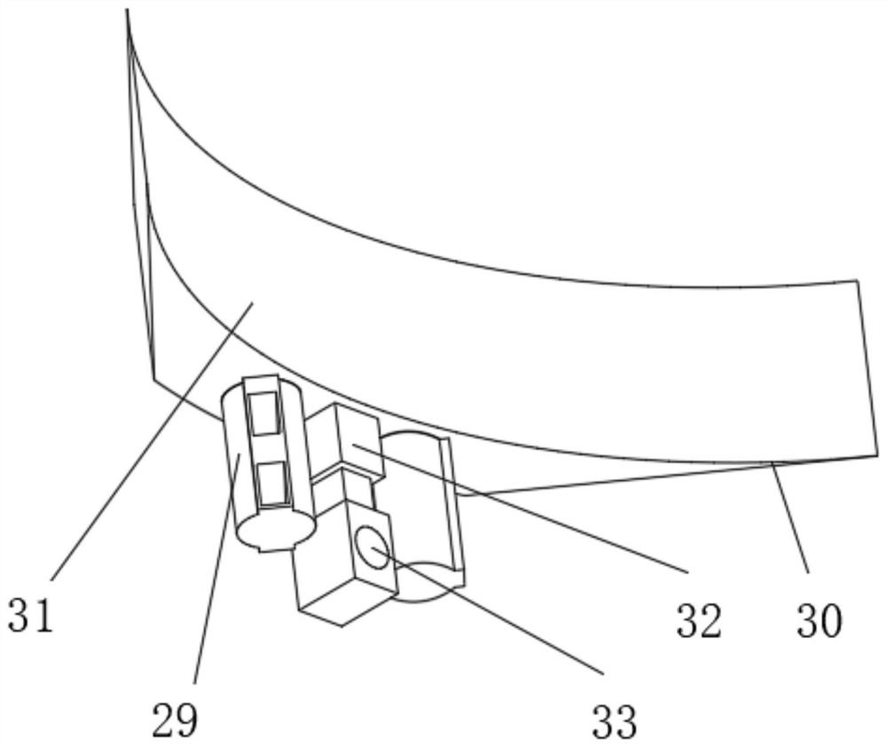
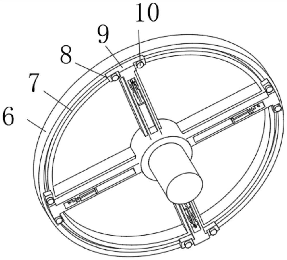
The invention relates to a clamping device with precision measurement for gear ring production and processing, the clamping device comprises a clamping base and a lower sealing mechanism, the peripheral outer wall of the clamping base is fixedly provided with side group stator plates, the end walls of the side group stator plates are provided with plate holes in a penetrating manner, and the end walls of four corners of the clamping base are provided with positioning screws in a penetrating manner; a penetrating channel is formed in the upper end wall of the clamping base, an inner assembly ring is arranged at the top end of the penetrating channel, a ring channel is formed in the end wall of the inner assembly ring, the lower sealing mechanism is arranged at the side end of the ring channel, and the upper jacking mechanism is arranged on the upper end wall of the clamping base. The clamping device with the precision measurement function for gear ring production and machining has the beneficial effects that the lower sliding block can be moved through matched movement between the lower sliding block and the ring way, and after the lower sliding block moves to the hollow area of the end of the inner assembly ring, supporting and padding can be conveniently conducted, and after the lower sliding block moves to the cross-shaped part of the end of the inner assembly ring, the device can be used for idle storage, is convenient to store, and is more convenient to control.

Description

technical field [0001] The invention relates to the technical field of ring gear production, in particular to a clamping device with precision measurement for ring gear production and processing. Background technique [0002] The ring gear is inlaid on the outer edge of the flywheel after being heated, and then fastened to the outer edge of the flywheel after cooling. It is used to mesh with the starter gear, drive the crankshaft to rotate, and start the engine. Generally, clamps are required for processing. The holding device is convenient and stable for processing and use. [0003] Due to the fact that the end of the existing clamping device is not designed with a good precision measurement structure, the accuracy of the clamping process is poor, and the measurement part cannot be moved very well, resulting in inconvenient manipulation. The support mode of the clamping part is single, and it is difficult to use the support part to simply support the ring gear, resulting i...

Claims


Application Information

Patent Timeline
Patent Type & Authority Applications(China)
IPC IPC(8): G01B5/00B25B11/00
CPCB25B11/00G01B5/0004G01B5/003
Inventor 赵梦逸赵磊孙晨昕蒋沭雷
Owner WUXI LONGDI PRECISED FORGINGS
Learn More