Integrated power unit including split crankcase with reinforced fastening arrangement, and vehicle including same

a technology of integrated power units and crankcases, which is applied in the direction of casings, machines/engines, coupling-brake combinations, etc., can solve the problems of difficult to contrive a more compact design of the vehicle body on the rear side, and achieve the effect of shortening the length of the rear end of the crankcase, enhancing the fastening force of the crankcase, and facilitating mounting

Inactive Publication Date: 2007-09-27
HONDA MOTOR CO LTD
View PDF4 Cites 12 Cited by
  • Summary
  • Abstract
  • Description
  • Claims
  • Application Information

AI Technical Summary

Benefits of technology

[0012]According to the integrated power unit for a small vehicle as set forth in the first aspect of the invention, the fastening boss portions at the rearmost portion of the plurality of pairs of fastening boss portions, are located at such positions as to overlap a rear portion of the clutch in the vehicle front-rear direction. Therefore, it is possible to shorten the length of rear end of the crankcase so that the rear side of the crankcase is closer to the front side of the power unit, whereby the design of the vehicle body on the rear side relative to the internal combustion chamber is more compact than that of a conventional power unit.
[0013]According to the integrated power unit for a small vehicle as set forth in the second aspect of the invention, the outside diameter of the driven gear, which together with the clutch mechanism forms the clutch, is set greater than the outside diameter of the clutch mechanism. In addition, the fastening boss portions, which are the fastening boss portions at the rearmost portion and which are located on the back side of the clutch, are formed at the same positions as the crank pins of the crankshaft, as seen when the power unit is viewed in the crankshaft direction. Therefore, at the time of mounting the clutch onto the transmission shaft, the driven gear can be mounted onto the transmission shaft in the manner of riding over the fastening boss portions while simultaneously releasing it into the space between the crank webs provided with the crank pins. Thus, ease of mounting the clutch on the transmission shaft is maintained.
[0014]In addition, since the fastening portions of the crankcase are set at positions close to a corner portion of the crankcase, the fastening forces for the crankcase are enhanced.

Problems solved by technology

The above described configuration makes it difficult to contrive a more compact design of the vehicle body on the rear side, relative to an internal combustion engine mounted on a small-type vehicle.

Method used


Image

  • Integrated power unit including split crankcase with reinforced fastening arrangement, and vehicle including same
  • Integrated power unit including split crankcase with reinforced fastening arrangement, and vehicle including same
  • Integrated power unit including split crankcase with reinforced fastening arrangement, and vehicle including same

Examples


Embodiment Construction

[0025]A selected illustrative embodiment of the invention will now be described in some detail, with reference to FIGS. 1 to 11. It should be understood that only structures considered necessary for clarifying the present invention are described herein. Other conventional structures, and those of ancillary and auxiliary components of the system, are assumed to be known and understood by those skilled in the art. In the following description, the forward travel direction of the vehicle is referred to as forward (front), the opposite direction is referred to as rearward (rear), and the respective left-hand and right-hand directions and / or sides are as viewed from a forward-facing vehicle operator.

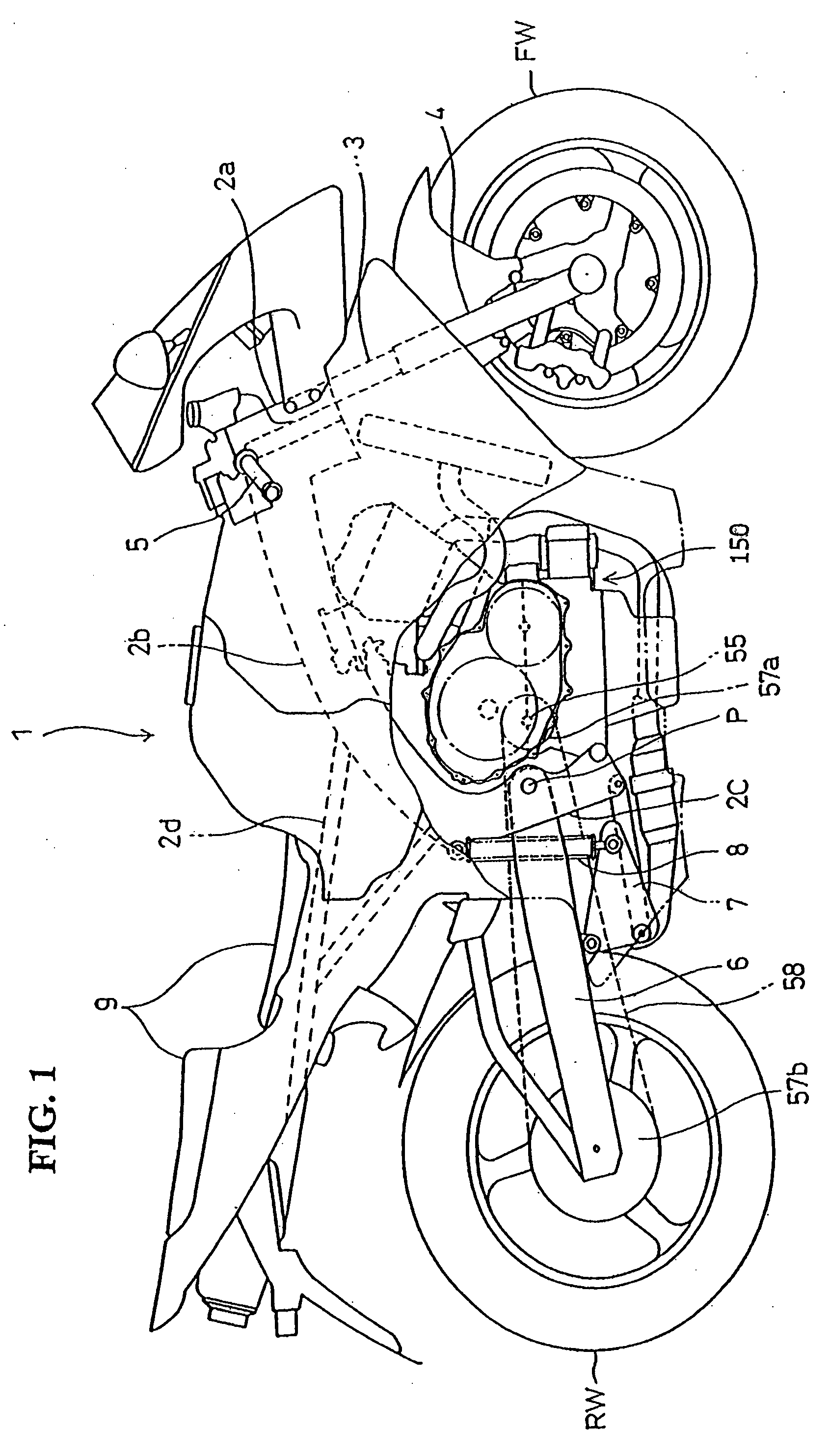
[0026]The above described small vehicle, on which the inventive integrated power unit 150 is mounted, is embodied by a motorcycle 1. An overall right side view of the motorcycle 1 is shown in FIG. 1.

[0027]A vehicle body frame of the motorcycle 1 has a configuration in which a main frame 2b ex...


PUM


Abstract

An integrated power unit for a small vehicle is configured to permit a compact engine design in a power unit having a crankcase that is split into upper and lower portions. The power unit includes a crankshaft supported by the crankcase and oriented transverse to the running direction of the vehicle. A transmission shaft is rotatably supported in a transmission chamber formed on the rear side of the crank chamber. The respective split surfaces of the upper and the lower crankcase portions are provided plural fastening boss portions arranged as vertically opposed pairs. The plural fastening boss portions are respectively joined using fastening bolts to integrate the upper crankcase and the lower crankcase, thereby forming the crankcase. A clutch is disposed at one end of the transmission shaft, and the rearmost fastening boss portions overlap with a rear portion of the clutch in the front-rear direction of the vehicle.

Description

CROSS-REFERENCE TO RELATED APPLICATIONS[0001]The present invention claims priority under 35 USC 119 based on Japanese patent application No. 2006-086352, filed on Mar. 27, 2006. The subject matter of this priority document is incorporated by reference herein.BACKGROUND OF THE INVENTION[0002]1. Field of the Invention[0003]The present invention generally relates to an integrated power unit for a small-type vehicle such as a motorcycle, wherein the integrated power unit includes an engine and a transmission, and has a crankcase which is split into upper and lower sections. The present invention particularly relates to an improved positioning of fastening bosses on a crankcase, the fastening bosses permitting fastening via fastening bolts of an upper crankcase to a lower crankcase.[0004]2. Description of the Background Art[0005]It is well known in the art to provide motorcycle engine having a crankcase which is split so as to provide an upper crankcase portion and a lower crankcase port...

Claims


Application Information

Patent Timeline
Patent Type & Authority Applications(United States)
IPC IPC(8): F02B75/32F02F7/00B60W10/02
CPCF02B75/20F02B61/02
Inventor HAZE, HIROTAKAKONO, NAOKI
Owner HONDA MOTOR CO LTD
Why Eureka
Try Eureka