

Radial lip seal device
A sealing device, radial shaft technology, applied in the direction of engine sealing, mechanical equipment, engine components, etc., can solve the problems of complex structure and large space, and achieve the effect of simple structure
- Summary
- Abstract
- Description
- Claims
- Application Information
AI Technical Summary
Problems solved by technology
Method used
Image

Examples
Embodiment Construction
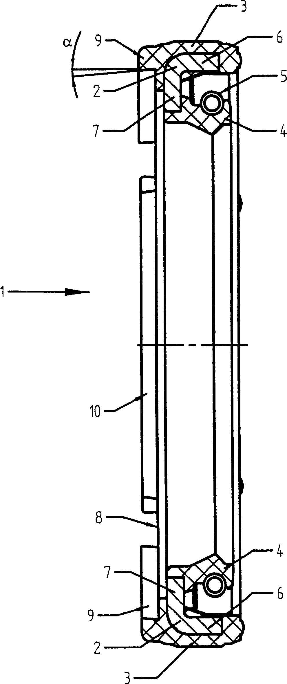
[0017] figure 1 A sealing ring 1 for a radial shaft seal is shown. The radial shaft sealing ring 1 forms a sealing assembly comprising a base body 2 of metal with an outer adhesive layer 3 of elastomer and a radially inwardly facing sealing lip 4 . The sealing lip 4 is likewise made of an elastomer and is additionally pressed against a shaft (not shown in detail) via a spring ring 5 . Seen in cross section, the base body 2 has an axial branch 6 and a radial branch 7 . Branches 6 and 7 are of equal length in the example shown.
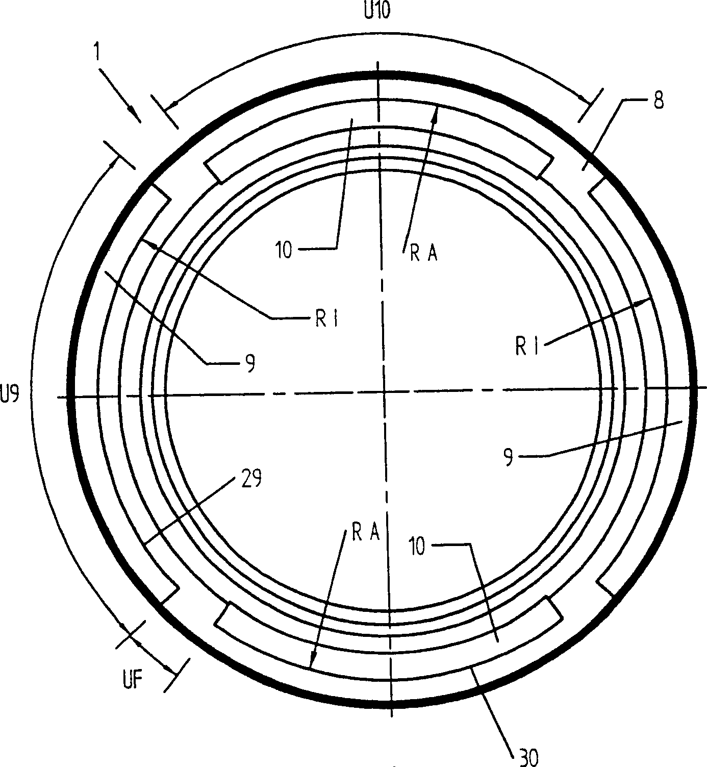
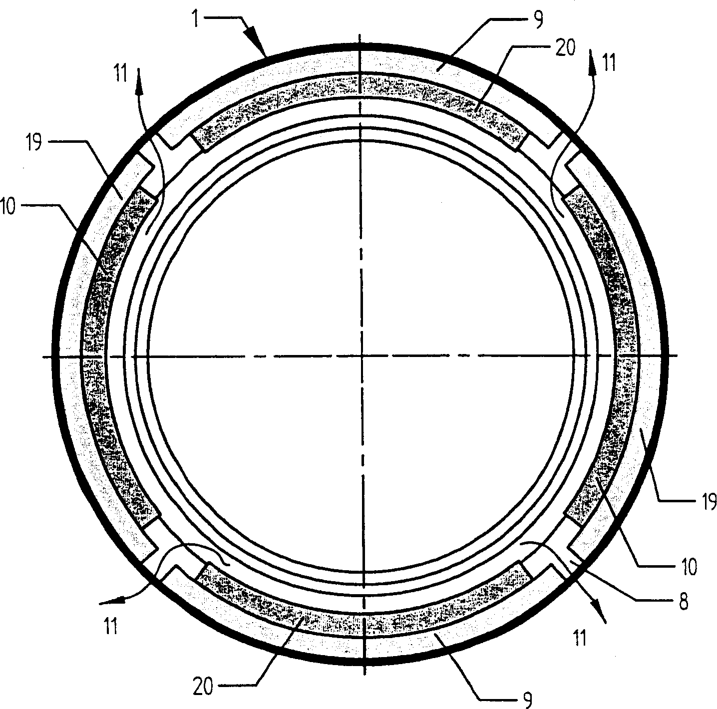
[0018] The inner surface 8 of the sealing ring 1 after the assembly of the two sealing rings is provided with four annular segments 9 and 10 which, in the assembled state of the two sealing rings 1 , engage with each other in a non-positive and form-fitting manner. Two of the ring segments 9 are offset radially outward and are referred to as outer ring segments 9 , while the inner ring segment 10 is offset radially inward. belongs to figure 1 The s...
PUM
| Property | Measurement | Unit |
|---|---|---|
| Cone angle | aaaaa | aaaaa |
Abstract
Description
Claims
Application Information