Multilayer filter media

a filter media and multi-layer technology, applied in the field of filter media, can solve the problems of engine corrosion in the decompression stage, reduced efficiency, and increased probability of gas turbine failur

Active Publication Date: 2015-05-07
CAMFIL AB
View PDF4 Cites 7 Cited by
  • Summary
  • Abstract
  • Description
  • Claims
  • Application Information

AI Technical Summary

Benefits of technology

[0003]It is an object of the present invention to provide an improved filter media which eliminates, or at least reduces the above mentioned and other drawbacks. This object and other objects are achieved by a filter media according to the prese

Problems solved by technology

This type of accumulation of unwanted material reduces efficiency and increases probability of failure of the gas turbine.
Insufficient filter performance can also cause engine corrosion in the decompression stage (hot end corrosion).
It has, however, been revealed that particles having a size below 0.4 μm have a significant impact on both fouling and hot end corrosion and this has lead to an increased demand for filters in higher filter classes.
A problem with these highly efficient filters is that they have a considerably higher pressure drop.
In existing gas turbines, this is not always possible, or at least not feasible for cost reasons

Method used


Image

  • Multilayer filter media
  • Multilayer filter media
  • Multilayer filter media

Examples


Embodiment Construction

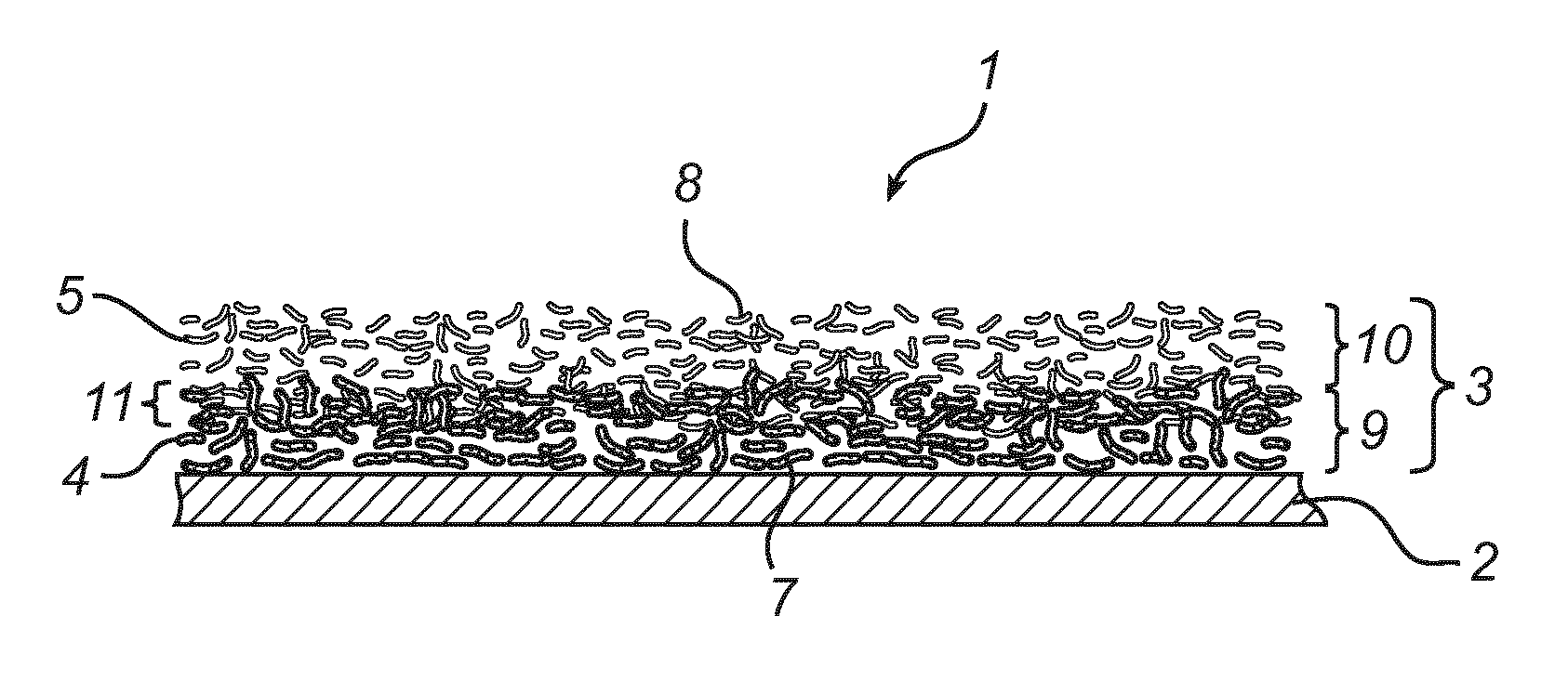
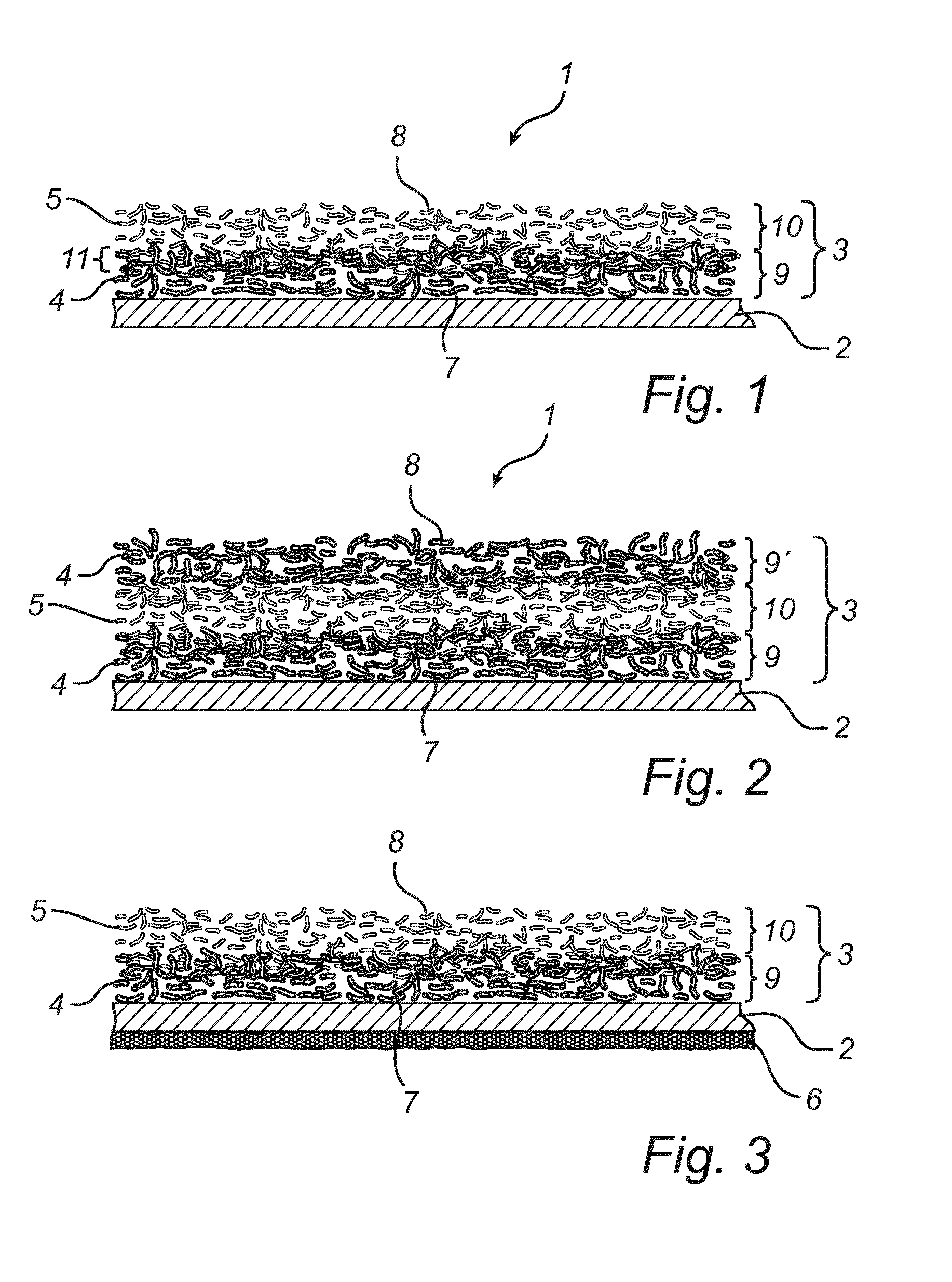
[0025]In a first embodiment of a filter media according to the invention, as shown in FIG. 1, a filter media 1 comprises a porous membrane layer 2.

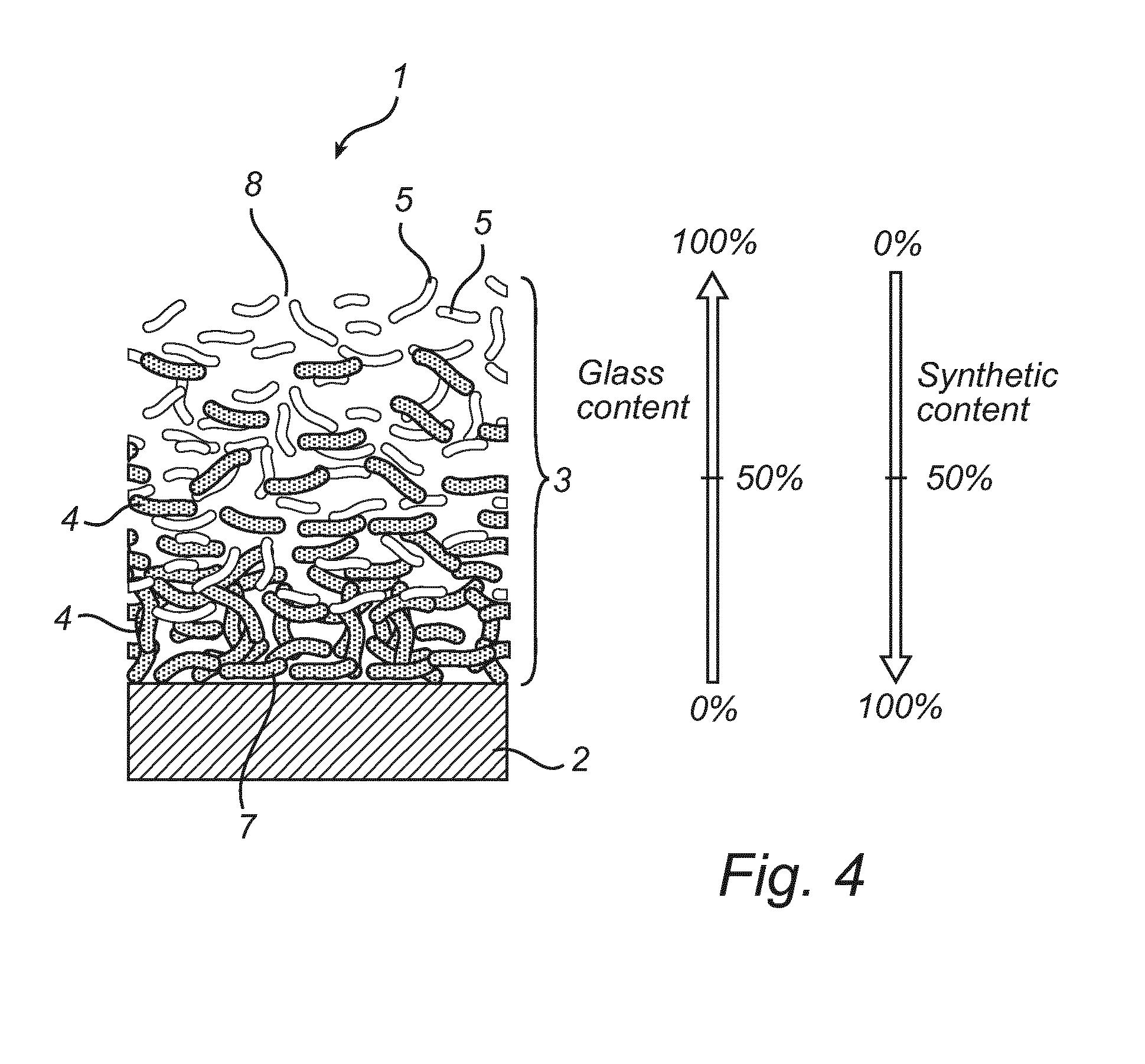
[0026]The membrane layer 2 could comprise an ePTFE-membrane or an UPE-membrane or an electro spun membrane made of fibers from a variety of polymers. The membrane 2 is laminated to a pre-filter media 3. This pre-filter media 3 is intended to protect the membrane 2 from mechanical damage and prevent larger particles from reaching the upstream surface of the membrane, thus preventing or at least reducing clogging of the membrane 2. The pre-filter layer comprises a downstream surface 7 with which the pre-filter layer 2 is laminated to an upstream surface of the membrane 2. The pre-filter layer 2 comprises two types of fibers divided in two somewhat overlapping layers 9 and 10. The upstream layer 10 comprises a majority of glass fibers 5 and the downstream layer 9 comprises a majority of synthetic fibers 4. It should be noted that these layer...


PUM

PropertyMeasurementUnit
Diameteraaaaaaaaaa
Diameteraaaaaaaaaa
Diameteraaaaaaaaaa

Abstract

A filter media is disclosed for removing particles from an air stream. The filter media, in an embodiment, includes a porous membrane layer and a pre-filter layer including a downstream surface and an upstream surface. The pre-filter layer is arranged with the downstream surface adjacent an upstream side of the porous membrane layer. The pre-filter layer includes a wet laid composite media having a mixture of glass fibers and synthetic fibers. A method for using the filter media in a gas turbine is also disclosed.

Description

FIELD OF THE INVENTION[0001]The present invention relates to a filter media for removing particles from an air flow and to the use of such filter media in a gas turbine.BACKGROUND OF THE INVENTION[0002]Gas turbines for e.g. power generation are normally protected by air filters provided in the air intake system. The purpose of these filters is to protect the engine from residue build-up, fouling, on the turbine blades in the compressor stage. This type of accumulation of unwanted material reduces efficiency and increases probability of failure of the gas turbine. Insufficient filter performance can also cause engine corrosion in the decompression stage (hot end corrosion). In the past, it was common to use filters in filter classes F7-F9 (EN779-2002) having a removal efficiency of almost 100% for particles above 3 μm but merely 50-75% for particles sized 0.4 μm and below. It has, however, been revealed that particles having a size below 0.4 μm have a significant impact on both fouli...

Claims


Application Information

Patent Timeline
IPC IPC(8): F02C7/05B01D46/00B01D46/54
CPCF02C7/05B01D46/0023B01D46/543B01D39/1623B01D39/1692B01D39/2017B01D2239/0435B01D2239/064B01D2239/065B01D2239/1233B01D46/62
Inventor LANS, ERIK
Owner CAMFIL AB
Why Eureka
Try Eureka