[0009]Generally, the invention relates to a
cartridge cushioning system that includes a
load distribution plate and functional elements. In accordance with the invention, the
load distribution plate serves as a support for the functional elements of the shoe sole, for example, lateral and medial deformation elements. The load distribution plate transmits and distributes the response of each element to external loads over the
forefoot region of the foot. Accordingly, the number, the arrangement, and the specific material properties of the elements contribute to selectively influence the course of motion of a wearer's foot, for example during rolling-off and push-off, to avoid supination or excessive pronation. As such, the independent deformation elements adapt exactly to the deformation needs of a specific area of the wearer's foot.
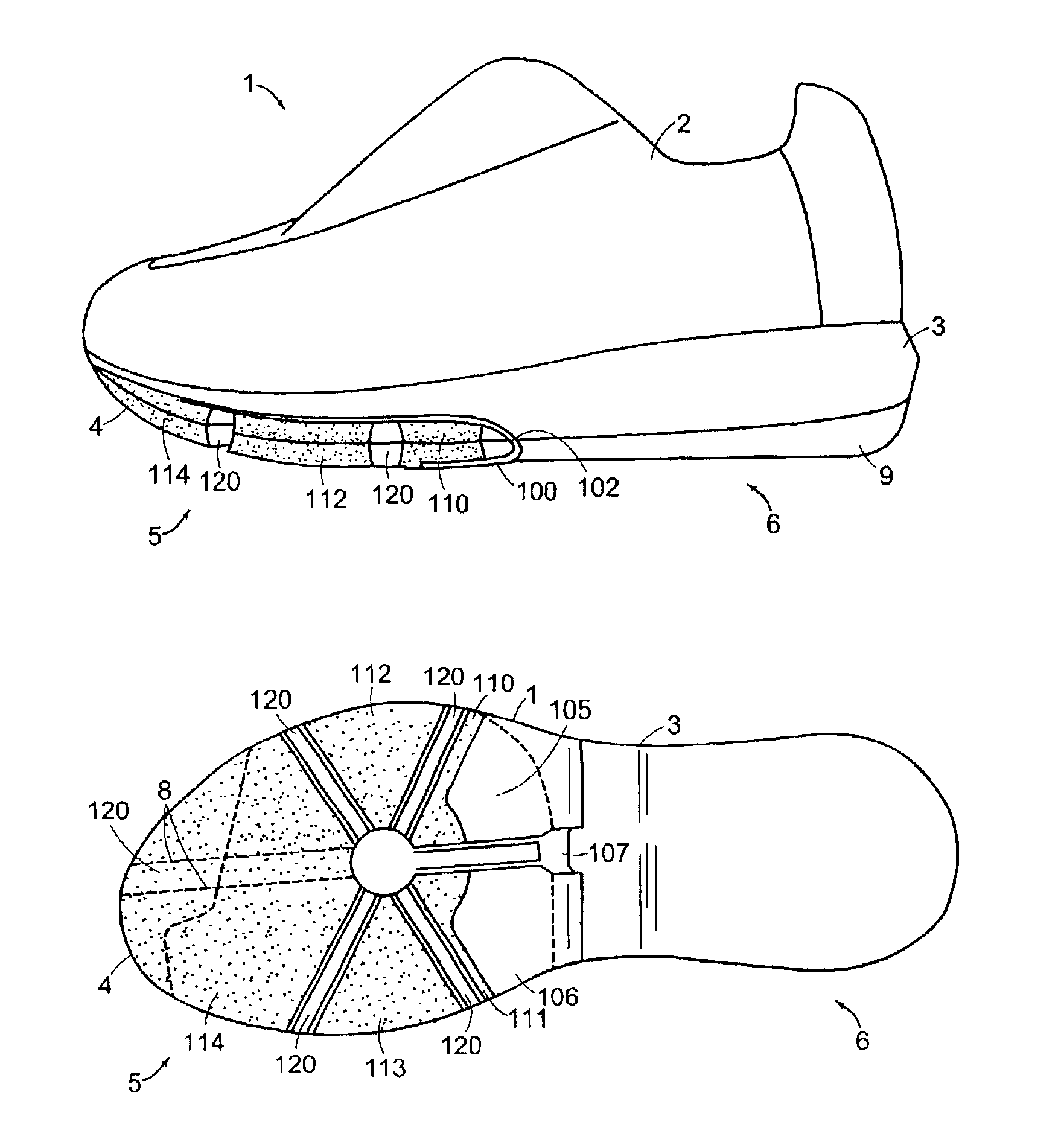
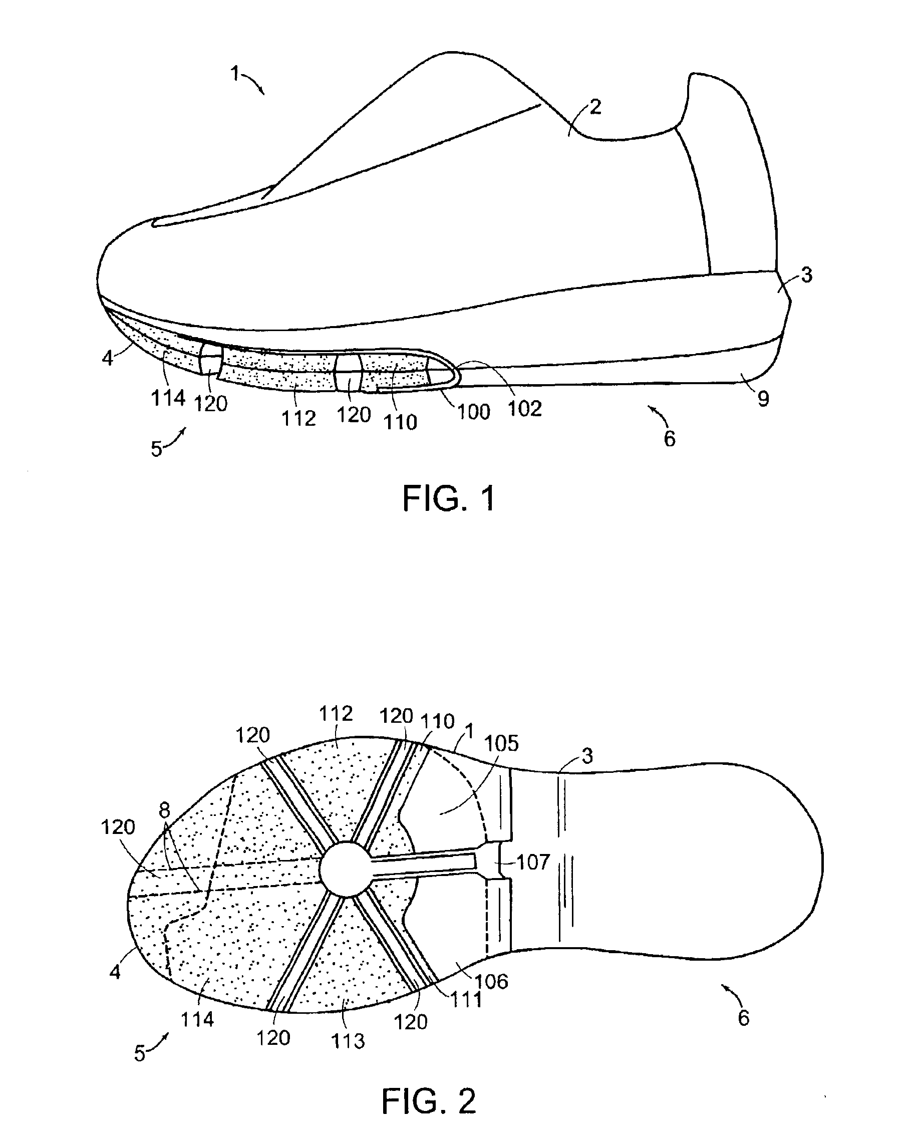
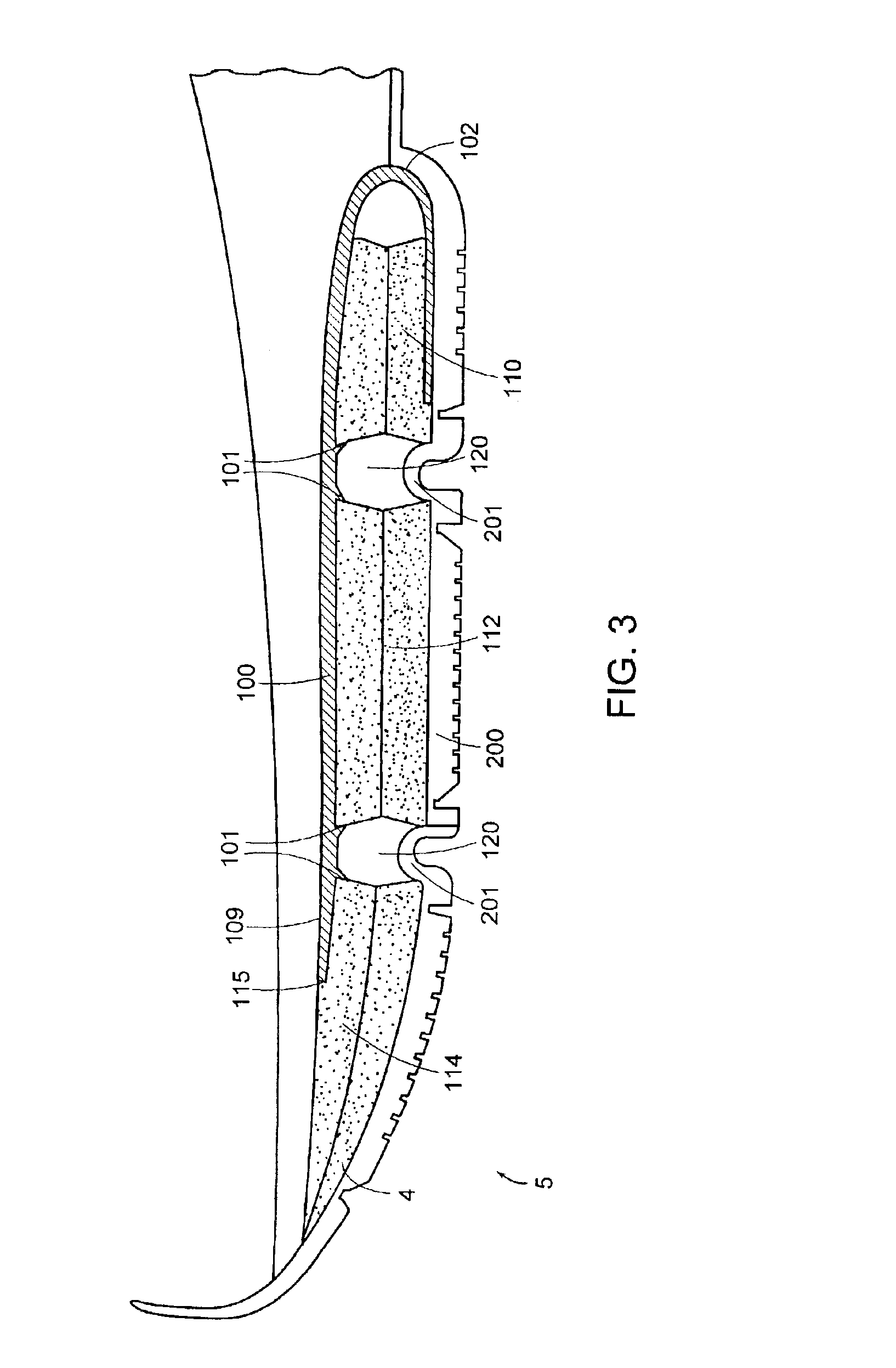
[0010]Because the load distribution plate encases the functional elements starting from an aft end of a forefoot region, the three-dimensional shape of the plate provides increased support for the arch region of the foot and a high degree of flexibility in the forefoot region, either for cushioning or
elastic energy storage. If it turns out that different deformation elements are more suitable to meet the present or changed requirements of the sole, the existing deformation elements can easily be replaced without having to make any other modification in the manufacturing process of the sole. Moreover, the overall weight of the sole may be reduced considerably by constructing the forefoot portion in accordance with the invention, with separately arranged forefoot elements instead of the continuously foamed material.
[0013]In various embodiments of the foregoing aspects, the lateral deformation element and the medial deformation element are spaced apart from each other to independently deform in response to a load on the sole, which is not possible where the elements are integrated into a surrounding EVA foam. The first load distribution plate has a generally recumbent U-shaped cross-sectional profile, wherein a closed end of the first load distribution plate is oriented towards the aft end of the forefoot region of the sole. This shape leads to increased
structural stability of the sole, since the deformation elements are encompassed by the load distribution plate from behind and from below. The first load distribution plate may further include a lateral lower side and a medial lower side, wherein each lower side can be independently deflected. In one embodiment, the lateral lower side and the medial lower side are separated from each other by, for example, a
cut section or gap. As such, the response properties of the sole on the
medial side can be independently adjusted from the response properties on the lateral side of the forefoot region. In one embodiment, the first load distribution plate includes an upper side extending further towards a front portion of the sole than at least one of the lateral lower side and the medial lower side.
[0016]Additionally, the sole may include a second load distribution plate disposed in a
heel region of the sole, at least one cushioning element disposed
proximate the second load distribution plate, and at least one guidance element disposed
proximate the second load distribution plate. The at least one cushioning element is configured and located to determine a cushioning property of the sole during a first
ground contact with the
heel region. The at least one guidance element is configured and located to bring a wearer's foot toward a
neutral position after the first
ground contact. The cushioning element protects the joints and muscles against the ground reaction forces arising during the first ground contact, while the material properties of the guidance element assure that even immediately after ground contact, pronation control occurs, bringing the foot into an intermediate position that is correct for this stage of the step cycle. The second load distribution plate in the
heel region assures uniform force distribution on the heel and assures that the cushioning and guiding effect of the elements is not restricted to single parts of the heel, but evenly transmitted to the complete
heel region. Thus, the foot is optimally prepared for the subsequent rolling-off phase of the forefoot region. In one embodiment, the sole also includes a stability element disposed
proximate the second load distribution plate, the stability element configured and located to control pronation during transition to a rolling-off phase of a step cycle.
[0017]In various embodiments, the at least one guidance element includes a lateral guidance element and a medial guidance element. The combined effect of these two elements, during ground contact with the shoe sole, enables the controlled transition of the
center of mass from the lateral rear side to the center of the heel. The cushioning element, the lateral guidance element, the medial guidance element, and the stability element each may be disposed generally within quadrants of the
heel region. In one embodiment, the cushioning element is generally located in a lateral rear quadrant, the lateral guidance element is generally located in a lateral forward quadrant, the medial guidance element is generally located in a medial rear quadrant, and the stability element is generally located in a medial forward quadrant, and at least two of the cushioning element, the lateral guidance element, the medial guidance element, and the stability element are spaced apart. This arrangement of the functional elements advantageously provides complete “pronation control” from the first ground contact until the transition to the rolling-off phase. After the cushioning compression of the cushioning element during the first ground contact, the diagonally arranged guidance elements guide the load of the center of gravity to the center of the heel. The stability element arranged in the medial front part assures that the center of gravity does not excessively shift to the
medial side in the course of a further turning of the foot.

