Battery pack case

a battery pack and case technology, applied in the field of battery pack cases, can solve the problems of battery pack structure degradation, assembly process, and large difficulty in maintaining arrangement structure, and achieve the effects of improving the structural stability of the battery pack and the safety of the battery pack, stably stacked, and simple assembly process

Active Publication Date: 2010-02-25
LG ENERGY SOLUTION LTD
View PDF21 Cites 76 Cited by
  • Summary
  • Abstract
  • Description
  • Claims
  • Application Information

AI Technical Summary

Benefits of technology

[0014]Consequently, the pack case according to the present invention has advantages in that a plurality of battery cells are stably mounted in the pack case in a compact structure through a simple assembly process, and heat generated from the battery cells is effectively removed during the charge and discharge of the battery cells, thereby improving the structural stability of the battery pack and the safety of the battery pack against fire.
[0015]The shape of the upper case and the lower case is not particularly restricted. Consequently, it is possible to manufacture the upper case and the lower case in various shapes. For example, the upper case and the lower case may be coupled with each other in a hexahedral structure such that the battery cells are stably stacked between the upper case and the lower case. Also, the upper case and the lower case may be manufactured in the same shape such that the upper case and the lower case are coupled with each other in a symmetrical structure. In this case, the upper case and the lower case may be coupled with each other without making a distinction between the upper case and the lower case during the assembly of the pack case, whereby high assembly efficiency is accomplished.

Problems solved by technology

Especially, cylindrical secondary batteries, which are used as the unit cells of the battery pack, have great difficulty in maintaining the arrangement structure due to the appearance characteristics thereof.
However, the spacers interfere with the flow of heat generated from the cylindrical secondary batteries during the charge and discharge of the cylindrical secondary batteries, thereby causing the degradation of the battery pack.
Also, the spacers are mounted to the battery pack as separate members with the result that the assembly process is complicated, and the manufacturing costs are increased.
However, the use of the spacers and the external case increases the volume and weight of the battery pack.

Method used


Image

  • Battery pack case
  • Battery pack case
  • Battery pack case

Examples


Embodiment Construction

[0035]Now, preferred embodiments of the present invention will be described in detail with reference to the accompanying drawings. It should be noted, however, that the scope of the present invention is not limited by the illustrated embodiments.

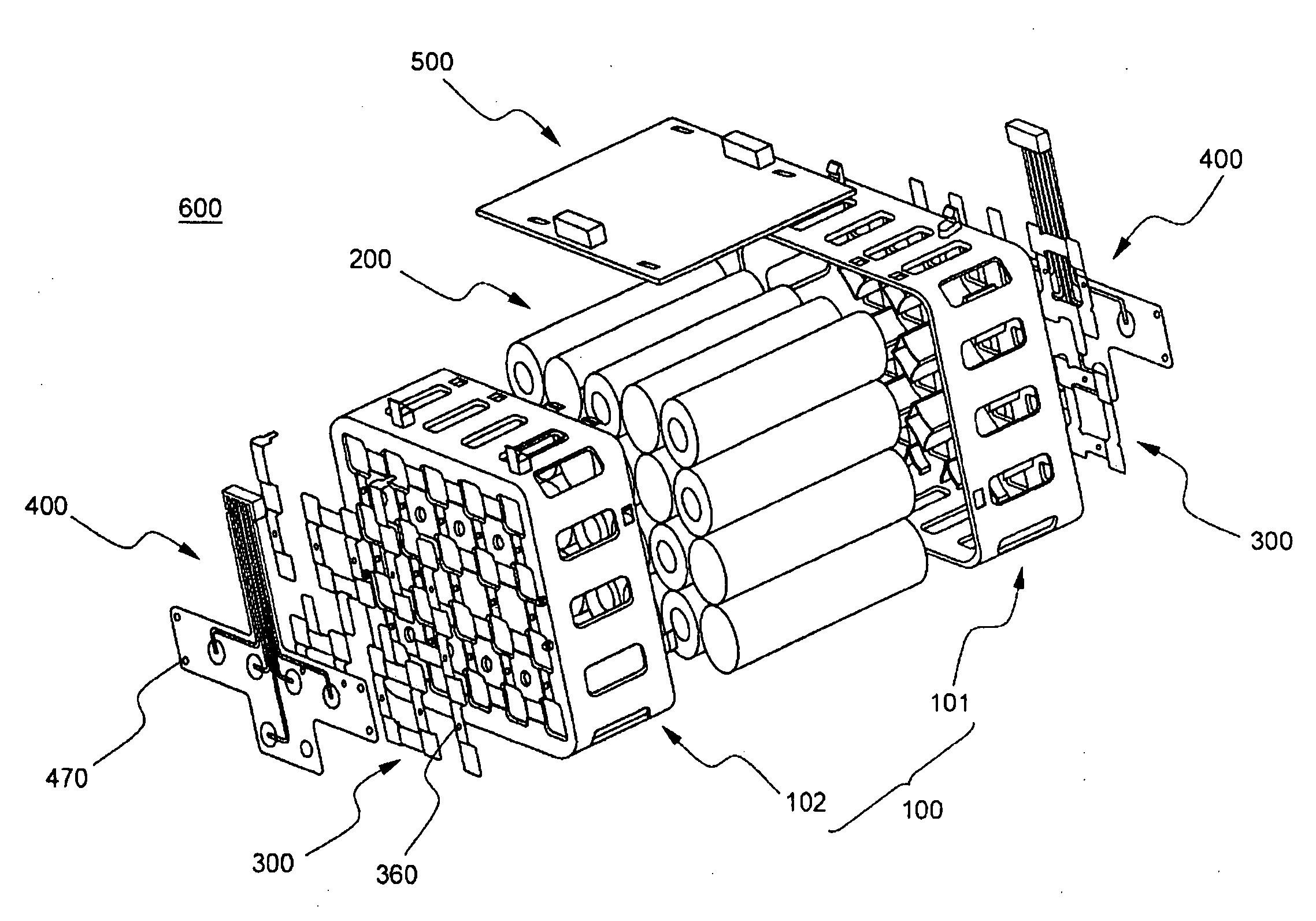
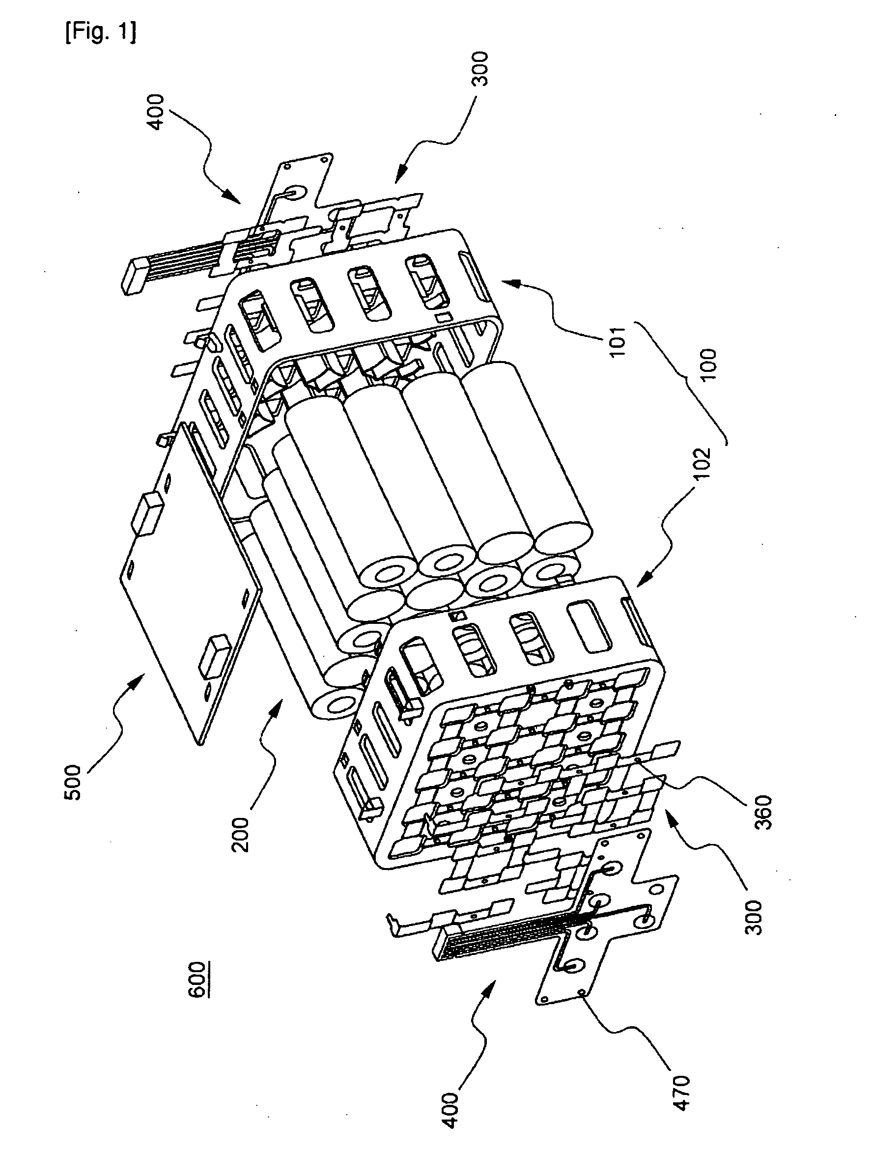
[0036]FIG. 1 is an exploded perspective view typically illustrating a battery pack according to a preferred embodiment of the present invention.

[0037]Referring to FIG. 1, the battery pack 600 includes a battery pack case 100 constructed in a structure in which a plurality of cylindrical battery cells 200 are mounted in the battery pack case 100, a metal plate 300 for electrically connecting the battery cells 200 with each other, a flexible printed circuit board (FPCB) 400 connected to the metal plate 300 for detecting the voltage of the battery cells 200, and a protection circuit unit 500 connected to the FPCB 400 for controlling the battery cells 200.

[0038]The battery pack case 100 includes an upper case 101 and a lower case 102, which are ...


PUM

PropertyMeasurementUnit
structureaaaaaaaaaa
circumferencesaaaaaaaaaa
voltageaaaaaaaaaa

Abstract

Disclosed herein are a pack case constructed in a structure in which a plurality of battery cells are mounted in the pack case to electrically connect the battery cells with each other, wherein the pack case includes an upper case and a lower case constructed in a hollow structure in which the upper case and the lower case are coupled with each other while the battery cells are mounted between the upper case and the lower case, each case is integrally provided at the inner part thereof with a plurality of spacers for supporting the battery cells, and each case is provided at the outer part thereof with a plurality of ventilation openings which communicate with the interior of each case, and a battery pack including the pack case. The pack case according to the present invention has effects in that a plurality of battery cells are stably mounted in the pack case in a compact structure through a simple assembly process, heat generated from the battery cells is effectively removed during the charge and discharge of the battery cells, and an additional safety unit, such as a detection member and/or a protection circuit module, is easily mounted to the pack case.

Description

TECHNICAL FIELD [0001]The present invention relates to a battery pack case, and, more particularly, to a pack case constructed in a structure in which a plurality of battery cells are mounted in the pack case to electrically connect the battery cells with each other, wherein the pack case includes an upper case and a lower case constructed in a hollow structure in which the upper case and the lower case are coupled with each other while the battery cells are mounted between the upper case and the lower case, each case is integrally provided at the inner part thereof with a plurality of spacers for supporting the battery cells, and each case is provided at the outer part thereof with a plurality of ventilation openings which communicate with the interior of each case.BACKGROUND ART [0002]As mobile devices have been increasingly developed, and the demand of such mobile devices has increased, the demand of secondary batteries has also sharply increased as an energy source for the mobil...

Claims


Application Information

Patent Timeline
Patent Type & Authority Applications(United States)
IPC IPC(8): H01M10/48H01M6/42H01M50/213H01M50/271H01M50/291H01M50/528H01M50/529H01M50/541
CPCH01M2/105H01M2/1077H01M10/0525H01M10/425H01M10/48Y02T10/7011H01M10/5014H01M10/5016H01M10/503H01M10/5065H01M10/5004H01M10/625H01M10/643H01M10/6235H01M10/613H01M10/6562Y02E60/10H01M50/213Y02P70/50H01M50/291H01M50/271H01M50/10H01M50/20Y02T10/70H01M50/30H01M10/052H01M2220/20H01M2220/30
Inventor PARK, JONGHOCHO, YONGHOSHIN, JOONYOUNG
Owner LG ENERGY SOLUTION LTD
Why Eureka
Try Eureka