Wind turbine with floating foundation

a technology of wind turbines and foundations, which is applied in the direction of floating buildings, floating islands, bulkheads/piles, etc., can solve the problems of low structural stability, unsatisfactory environmental protection, and high cost of solution, so as to reduce the weight of parts and improve structural stability. stability, the effect of reducing the price of the foundation

Inactive Publication Date: 2007-01-02
VESTAS WIND SYST AS
View PDF9 Cites 92 Cited by
  • Summary
  • Abstract
  • Description
  • Claims
  • Application Information

AI Technical Summary

Benefits of technology

[0006]On the above background it is thus an object of the present invention to provide a wind turbine with a floating foundation of the tension leg type, in which an improved structural stability is attained and according to which a significant reduction of the weight of the part of the structure connecting the tower of the wind turbine with the buoyancy bodies can nevertheless be obtained. This weight reduction results among other things in a significant reduction of the price of the foundation and it also facilitates handling of the structure during transport from a harbour to the offshore site of the installation as well as during the final installation of the structure on site.
[0007]It is a further object of the present invention to provide a foundation, in which wave loads on the foundation are reduced.

Problems solved by technology

Such large collections of wind turbines can provide an environmentally less desirable solution both from an aesthetic point of view and also due to the inevitable noise problems they cause.
Furthermore, the positioning of wind turbines on land may not always be an optimal placement, as it is preferable that the blades of the wind turbine be located in a laminate flow of air which is not always obtained on land due to for instance the presence of hills, woods, buildings, etc.
This is not in principle a problem for wind turbines located on the ground but becomes a problem in connection with offshore wind turbines.
One prior art solution is to mount the tower of the wind turbine on a suitable construction of pillows and grids, this construction being fixed to a firm foundation on the bottom of the sea, but this solution is expensive and primarily applicable at relatively shallow waters, i.e. up to depths of around 25 meters.
However, the wires between the buoyancy bodies and the top portion of the tower can not be applied in systems where the nacelle must be relatable relative to the tower, which is necessary, when the buoyancy body or -bodies are fixed to the bottom of the sea in a manner that prevents rotation of the buoyancy bodies about the longitudinal axis through the tower.
Such wire stiffeners would at any rate not provide a solution of satisfactory stability in systems with high towers and hence long wires.

Method used


Image

  • Wind turbine with floating foundation
  • Wind turbine with floating foundation
  • Wind turbine with floating foundation

Examples


Embodiment Construction

[0023]In the following, a detailed description of an embodiment of the floating tension leg foundation for wind turbines according to the invention is given.

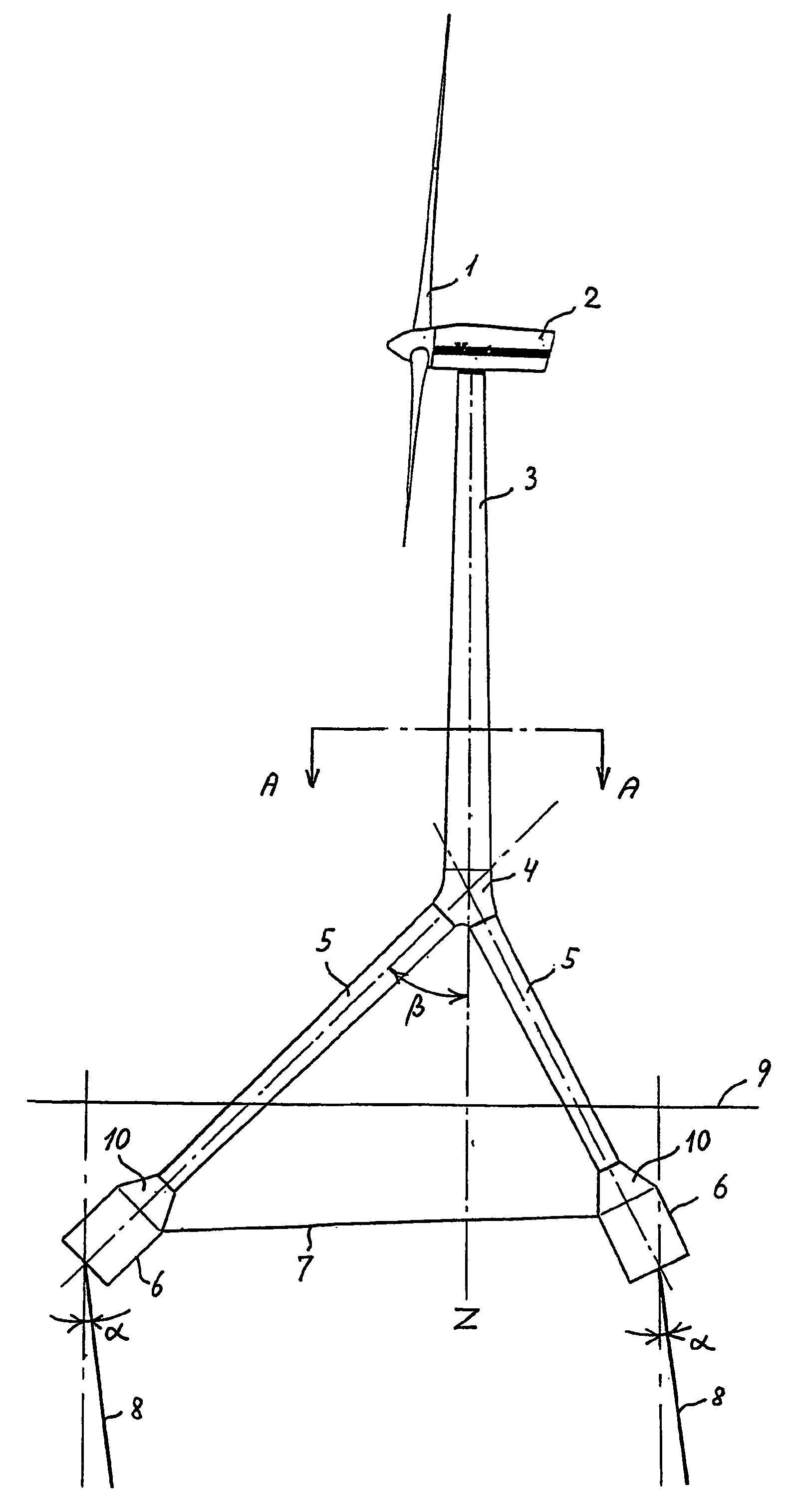
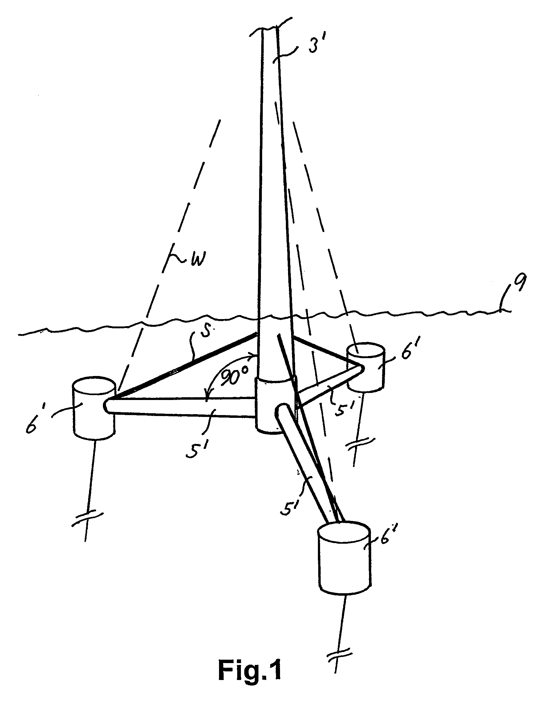
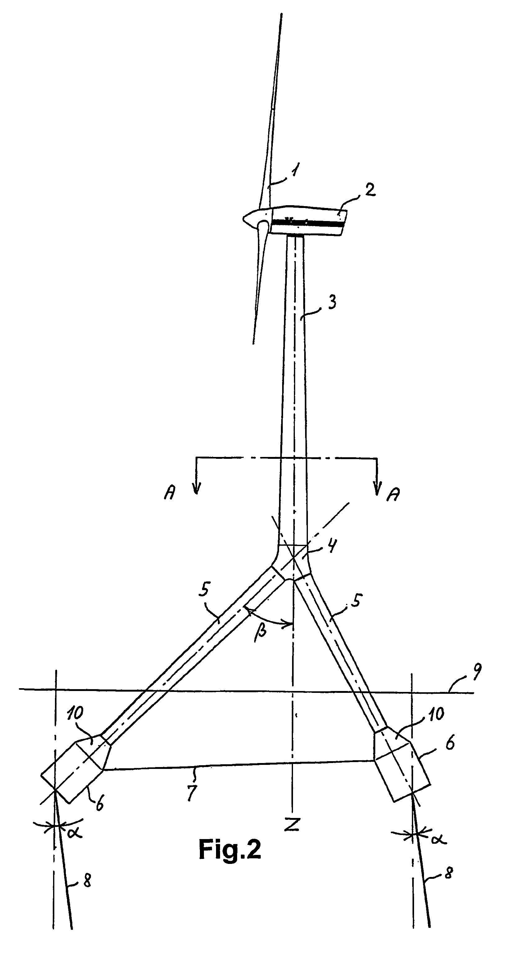
[0024]A presently preferred embodiment of the invention is shown in FIGS. 2 and 3. A wind turbine comprising a rotor 1 and a nacelle 2 is placed at the upper end of the tower 3. The lower end of the tower 3 is connected to a node member 4, from which node member three leg sections 5 extend downwardly at an angle β relative to the vertical axis Z through the tower 3. As shown in FIG. 3, the three leg sections are distributed in the horizontal plane at identical angular intervals of 120 degrees.

[0025]At the ends of the leg sections 5 there are provided buoyancy bodies 6, in the shown embodiment in the form of a cylindrical body connected to the leg sections 5 via a conical transition member 10. One separate buoyancy body is connected to each of the leg sections. Although the buoyancy bodies are shown as cylindrical bodies in this ...


PUM


Abstract

A floating foundation for wind turbines is disclosed, where the foundation essentially comprises at least three submerged buoyancy bodies connected to the lower end of the tower of the wind turbine at a common node member situated well above the surface of the sea. The buoyancy bodies are connected to the node member by means of relatively thin leg sections, whereby wave load on the foundation is reduced. By applying the foundation according to the present invention, stress concentrations and torques in the node member are reduced, whereby it becomes possible to apply a relatively lightweight and hence cheap node member. The overall weight of the construction is thereby reduced and hence the volume of the buoyancy bodies necessary to counteract the overall weight of the construction.

Description

TECHNICAL FIELD[0001]The present invention relates to wind turbines with floating foundations and more particularly to such wind turbines for use in offshore installations at greater water depths and under conditions where the installation is subjected to both heavy wind loads and to great dynamic forces from the movement of the sea.BACKGROUND OF THE INVENTION[0002]Wind turbines for converting wind energy to electrical power have been known and applied for many years but have found a dramatically increased application as an alternative energy source during the last couple of decades. It has become common to place wind turbines together in large groups of turbines often counting hundreds of wind turbines within a restricted area. Such large collections of wind turbines can provide an environmentally less desirable solution both from an aesthetic point of view and also due to the inevitable noise problems they cause. Furthermore, the positioning of wind turbines on land may not always...

Claims


Application Information

Patent Timeline
Patent Type & Authority Patents(United States)
IPC IPC(8): F03D11/04B63B35/00B63B35/44F03D1/00
CPCB63B35/44F03D11/045B63B2035/446E02B2017/0091Y02E10/727F05B2240/93F05B2240/95F03D13/22F03D13/25Y02E10/72B63B2241/16
Inventor NIM, ERIK
Owner VESTAS WIND SYST AS
Why Eureka
Try Eureka