
Method, an implement and a twister for tying together end portions of wire material extending around a bale

a technology of wire material and end portions, which is applied in the direction of bundling articles, manufacturing tools, and bundling machine details, etc., can solve the problems of material being easily entangled in the processing apparatus, material being cumbersome, and being difficult to remov

Inactive Publication Date: 2010-04-06
MACHINEFAB BOLLEGRAAF APPINGEDAM
View PDF17 Cites 7 Cited by
  • Summary
  • Abstract
  • Description
  • Claims
  • Application Information

AI Technical Summary

Benefits of technology

This approach allows for reliable interconnection of plastic wire around bales, reducing the tendency for untwisting and enhancing the strength of the twisted sections, while being easier to implement and maintain than previous methods.

Problems solved by technology

Although steel wire may be tied reliably by twisting, its separation from the baled material during or after processing and even after incineration of the material is cumbersome and it can easily become entangled in processing apparatus from which it is difficult to remove.
Other disadvantages of steel wire are that the twisted sections of the wire material are relatively weak compared with the strength of non twisted sections and that remainders of the material and rust forms a hazard where wire is used to bale animal feed.
However, plastic wire allows a much larger elastic deformation, before it is deformed plastically and therefore exhibits much more tendency to spring back and thereby untwist after twisting than steel wire.
Accordingly, it is has been found difficult to connect wires of plastic material by twisting.
This, however, requires a complicated construction.

Method used


Image

  • Method, an implement and a twister for tying together end portions of wire material extending around a bale
  • Method, an implement and a twister for tying together end portions of wire material extending around a bale
  • Method, an implement and a twister for tying together end portions of wire material extending around a bale

Examples


Embodiment Construction

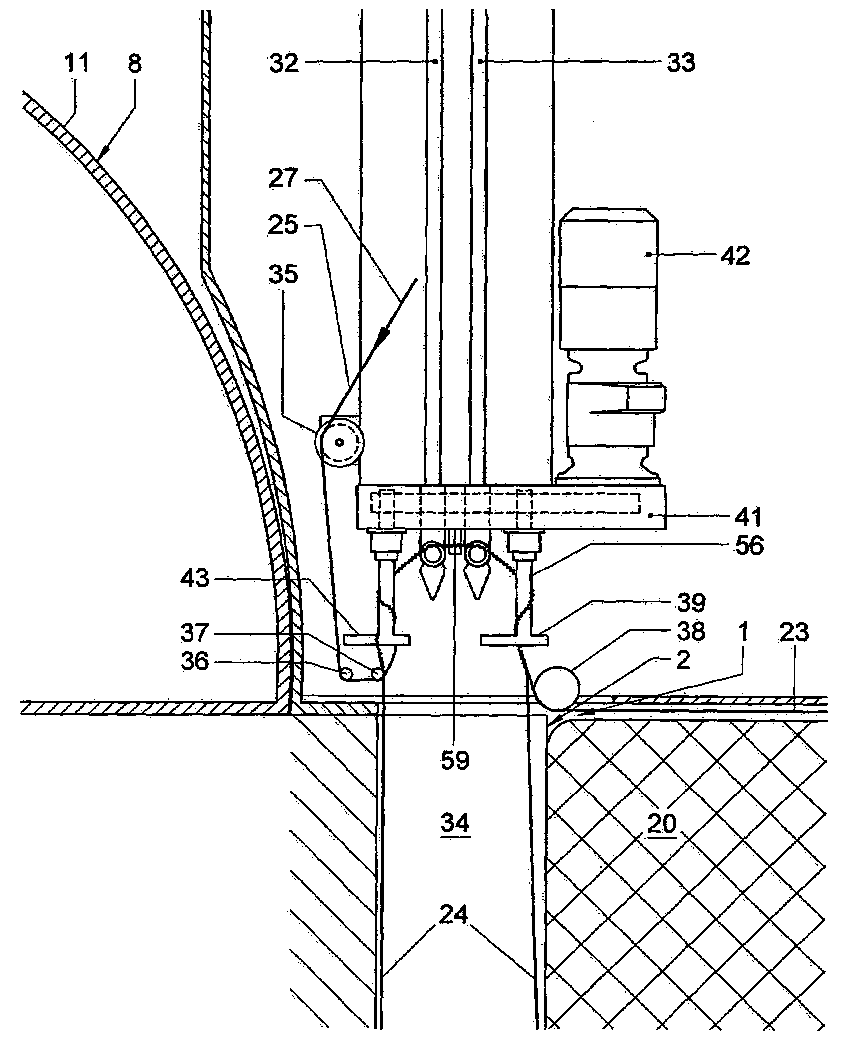
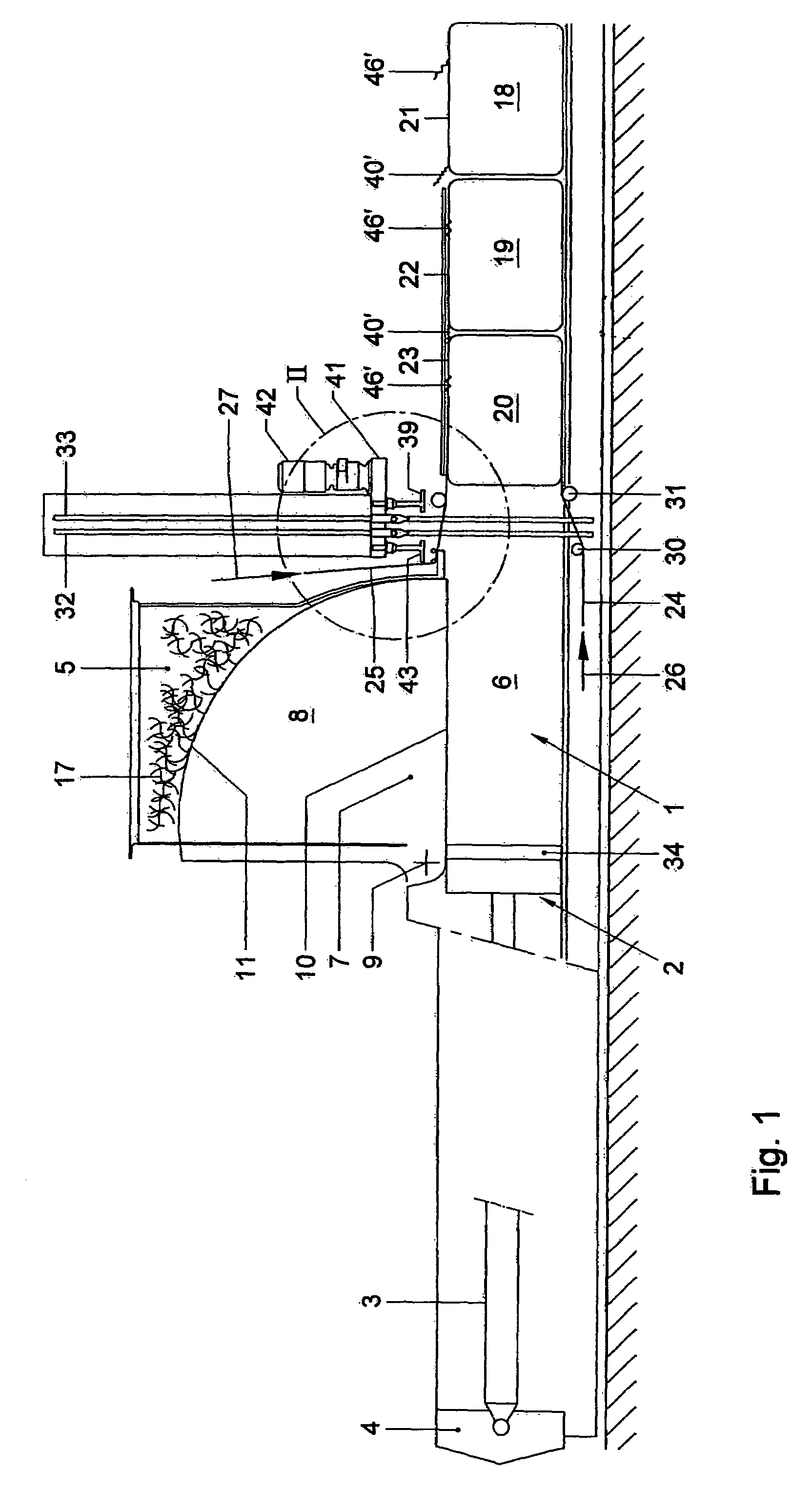
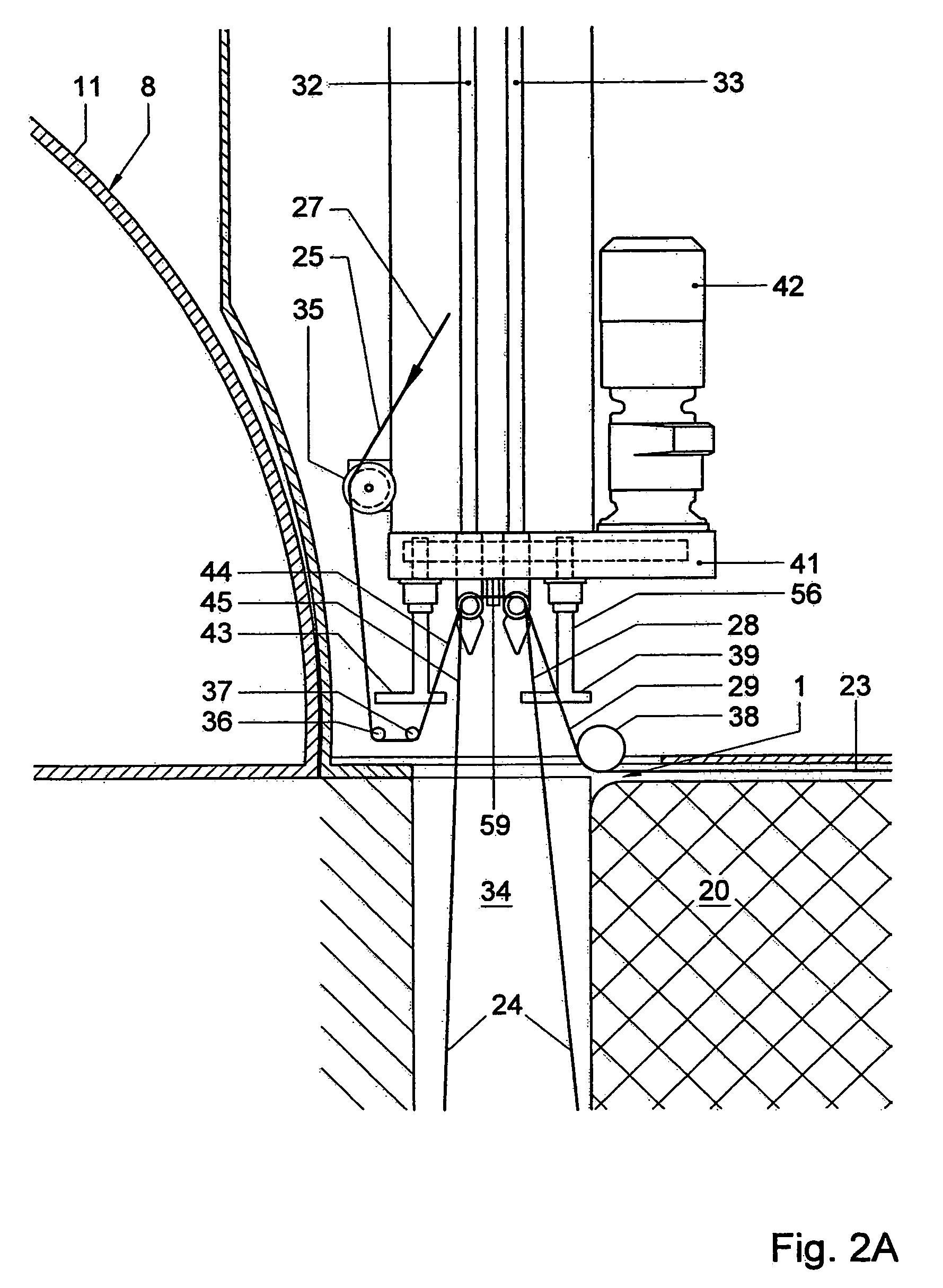
[0035]The baling press shown in FIG. 1 has a pressing channel 1 in which a ram 2 is displaceable by a piston 3 mounted between the ram 2 and a suspension bracket 4. The ram 2 is shown in its most retracted position. A feed chute 5 communicates with a pressing chamber area 6 of the pressing channel 1 via a passage 7 forming a downstream end of the feed chute 5.

[0036]A prepress valve 8 is pivotable about a pivotal axis 9 and has a flat wall 10 which, in closed position, closes off the passage from the feed chute 5 to the pressing channel 1 and, in opened position, is disposed in a wall of the feed chute 5. The prepress valve 8 furthermore has a surface 11 substantially curved around the pivotal axis 9, which surface in closed position bounds the feed chute 5 in axial direction.

[0037]Material 17 to be pressed may already be deposited into the feed chute 5, while the prepress valve 8 is closed. When the prepress valve 8 is opened, material to be pressed partially drops into the pressing...


PUM

PropertyMeasurementUnit
friction coefficientaaaaaaaaaa
thicknessaaaaaaaaaa
thicknessaaaaaaaaaa

Abstract

For tying wire material around a bale, a pair of end portions of the loop is held in a substantially mutually parallel orientation. An engaged section of at least one of the end portions is moved about a longitudinal axis of the other end portion of that pair, such that the pair of end portions is twisted into a wire twist between an engagement area and a portion of the loop extending about the bale. During twisting, wire material of at least one of the end portions slips through the engagement area towards the portion of the loop extending about the bale. An implement and twisters for use in such a method are also described.

Description

CROSS-REFERENCE TO RELATED APPLICATION[0001]This application claims the benefit of U.S. Provisional Patent Application Ser. No. 60 / 737,285 filed Nov. 16, 2005, the contents of which are incorporated herein by reference.TECHNICAL FIELD AND BACKGROUND ART[0002]The present invention relates to a method, an implement and a twister for tying together end portions of wire material extending around a bale.[0003]To facilitate storage, handling and transportation of loose material, such as waste paper and cardboard, waste plastic, straw, it is usual to press the material into bales.[0004]To prepare the bales, the material is pressed in a baling press. A baling press typically includes a baling channel in which a pressing ram is reciprocally movable to and fro, new material to be baled being added each time after the press has been retracted. The counter pressure against which the bales are pressed is obtained by resistance encountered by the material as it is pressed through the pressing cha...

Claims


Application Information

Patent Timeline
Patent Type & Authority Patents(United States)
IPC IPC(8): B21F45/00B21F15/04B21F7/00B65B13/02B65B13/28
CPCA01F15/146B65B27/12B65B13/28B30B9/3003
Inventor LEGTENBERG, HERMANNUS JOHANNES MARIASMIT, KLAAS
Owner MACHINEFAB BOLLEGRAAF APPINGEDAM
Learn More