
Speaker Assembly

a technology for loudspeakers and components, applied in the direction of transducer details, loudspeaker casing supports, electrical transducers, etc., can solve the problems of difficult to integrate high fidelity systems within aircraft, spend considerable time traveling, and especially pronounced problems for audio loudspeaker assemblies

Active Publication Date: 2010-05-13
TRACY DENNIS A
View PDF9 Cites 16 Cited by
  • Summary
  • Abstract
  • Description
  • Claims
  • Application Information

AI Technical Summary

Benefits of technology

[0009]It is, therefore, an object of the present invention to provide a speaker assembly including a speaker housing with a closed top wall, an opposed open end and first, second, third and fourth sidewalls extending downwardly from the closed top wall. The closed top wall is substantially planar and forms a support surface. First and second midrange drivers and first and second high frequency drivers are mounted within the housing, wherein the first midrange driver and the first tweeter are mirror images of second midrange driver and the second tweeter. A first support bracket supports the f

Problems solved by technology

For many people, this requires they spend considerable time traveling from one location to another location.
However, while high quality entertainment, for example, digital video with CD quality sound, is readily available for theater and home use, the weight and size requirements for use in aircraft make it very difficult to incorporate high fidelity systems within an aircraft.
This problem is especially pronounced for audio loudspeaker assemblies when one attempts to meet the size, weight and shape requirements for use in aircrafts.
The size, weight and shape of conventional terrestrial loudspeaker assembly designs adversely affect range and payload.
For example, a small increase in the weight carried by an aircraft results in a substantial increase in fuel consumption of the aircraft.
These loudspeakers, however, substantially compromise sound quality for reductions in size and weight.

Method used


Image

  • Speaker Assembly
  • Speaker Assembly
  • Speaker Assembly

Examples


Embodiment Construction

[0034]The detailed embodiments of the present invention are disclosed herein. It should be understood, however, that the disclosed embodiments are merely exemplary of the invention, which may be embodied in various forms. Therefore, the details disclosed herein are not to be interpreted as limiting, but merely as a basis for teaching one skilled in the art how to make and / or use the invention.

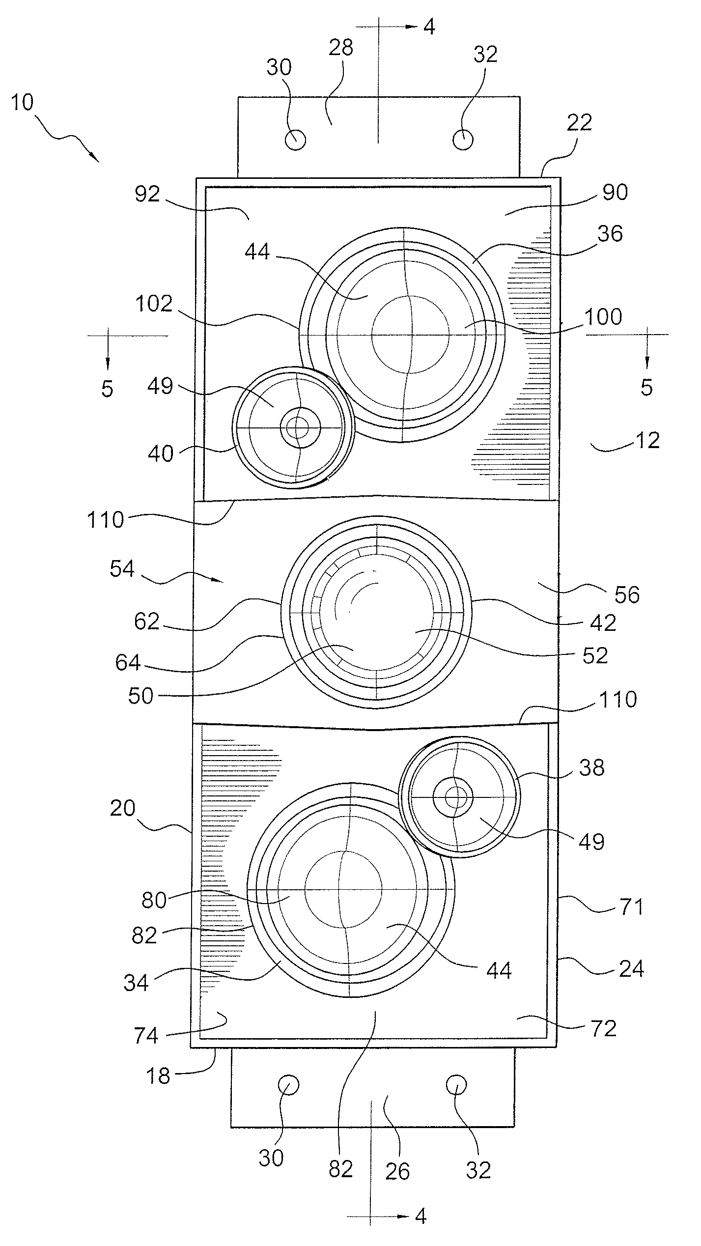
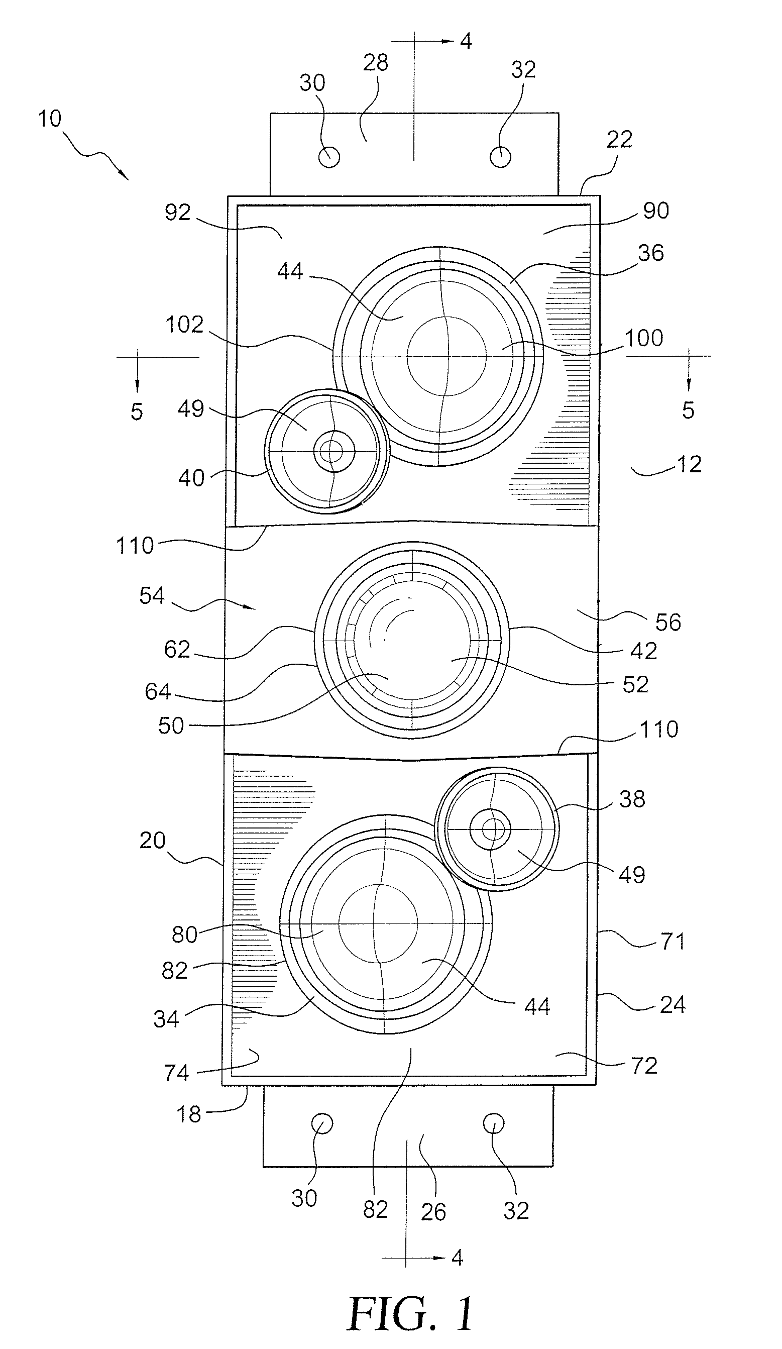
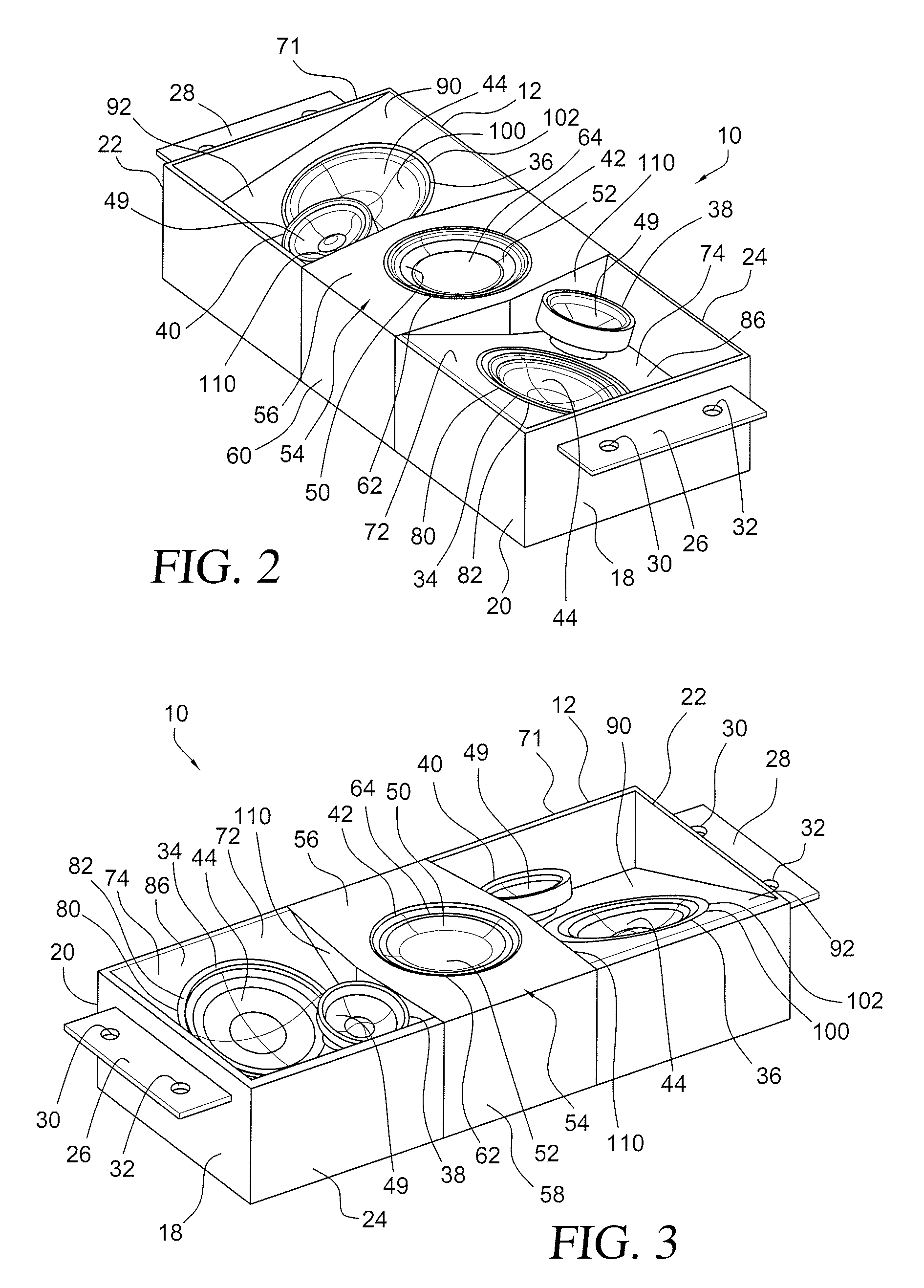
[0035]In accordance with the present invention, and with reference to FIGS. 1 to 5, a small profile speaker assembly 10 shaped and dimensioned for use within an aircraft is disclosed. The speaker assembly 10 incorporates a variety of features which reduce the size and weight of the speaker assembly 10 without compromising the integrity of the sound generated by the speaker assembly 10. The speaker assembly 10 is primarily intended for use in aircraft, where weight and size are critical. While the speaker assembly 10 is preferably designed for use in aircraft, the speaker assembly 10 may be used...


PUM


Abstract

A speaker assembly includes a speaker housing with a closed top wall, an opposed open end and first, second, third and fourth sidewalls extending downwardly from the closed top wall. The closed top wall is substantially planar and forms a support surface. First and second midrange drivers and first and second high frequency drivers are mounted within the housing, wherein the first midrange driver and the first tweeter are mirror images of second midrange driver and the second tweeter. A first support bracket supports the first midrange driver and first tweeter along a first side of the closed top wall adjacent the first sidewall of the speaker housing. The first support bracket includes a planar support surface which is obliquely oriented relative to a plane in which the closed top wall lies. A second support bracket supports the second midrange driver and the second tweeter along a second side of the closed top wall adjacent the third sidewall of the speaker housing. The first support bracket includes a planar support surface which is obliquely oriented relative to the plane in which the closed top wall lies.

Description

CROSS REFERENCE TO RELATED APPLICATION[0001]This application claims the benefit of U.S. Provisional Patent Application Ser. No. 61 / 113,376, entitled “SPEAKER ASSEMBLY”, filed Nov. 11, 2008.BACKGROUND OF THE INVENTION[0002]1. Field of the Invention[0003]The invention relates to a speaker assembly. More particularly, the invention relates to a speaker assembly with reduced size and weight to enhance the performance of the speaker assembly within an aircraft.[0004]2. Description of the Related Art[0005]The current global community has made it possible for people all around the country, and around the world, to interact for both business and personal reasons. For many people, this requires they spend considerable time traveling from one location to another location. More often than not, these people travel in aircraft. Whether these people travel in private or commercial aircraft, they desire high quality entertainment during the many hours they spend within the confines of an aircraft....

Claims


Application Information

Patent Timeline
IPC IPC(8): H04R1/00
CPCH04R1/026H04R1/26H04R2499/13H04R2307/023H04R2205/022
Inventor TRACY, DENNIS A.
Owner TRACY DENNIS A
Learn More