Blind cutter

Inactive Publication Date: 2010-05-27
CHEN CHIN FU
View PDF5 Cites 7 Cited by
  • Summary
  • Abstract
  • Description
  • Claims
  • Application Information

AI Technical Summary

Benefits of technology

[0006]The present invention has been accomplished in view of the above-noted circumstances. It is one objective of the present invention t

Problems solved by technology

However, when the cutting action of the blind cut down machine has been finished, the user needs to force the saw blade to move back to an initial position by manual operation or using a pneumatic cylinder, resulting in that the blind cut-down apparatus has the drawback of inconvenient operation.

Method used


Image

  • Blind cutter
  • Blind cutter
  • Blind cutter

Examples


Embodiment Construction

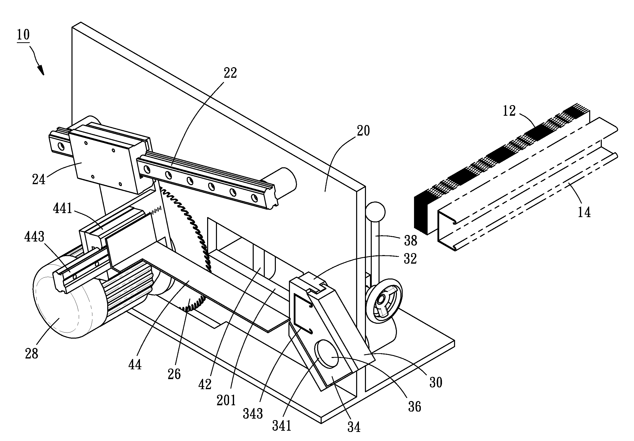
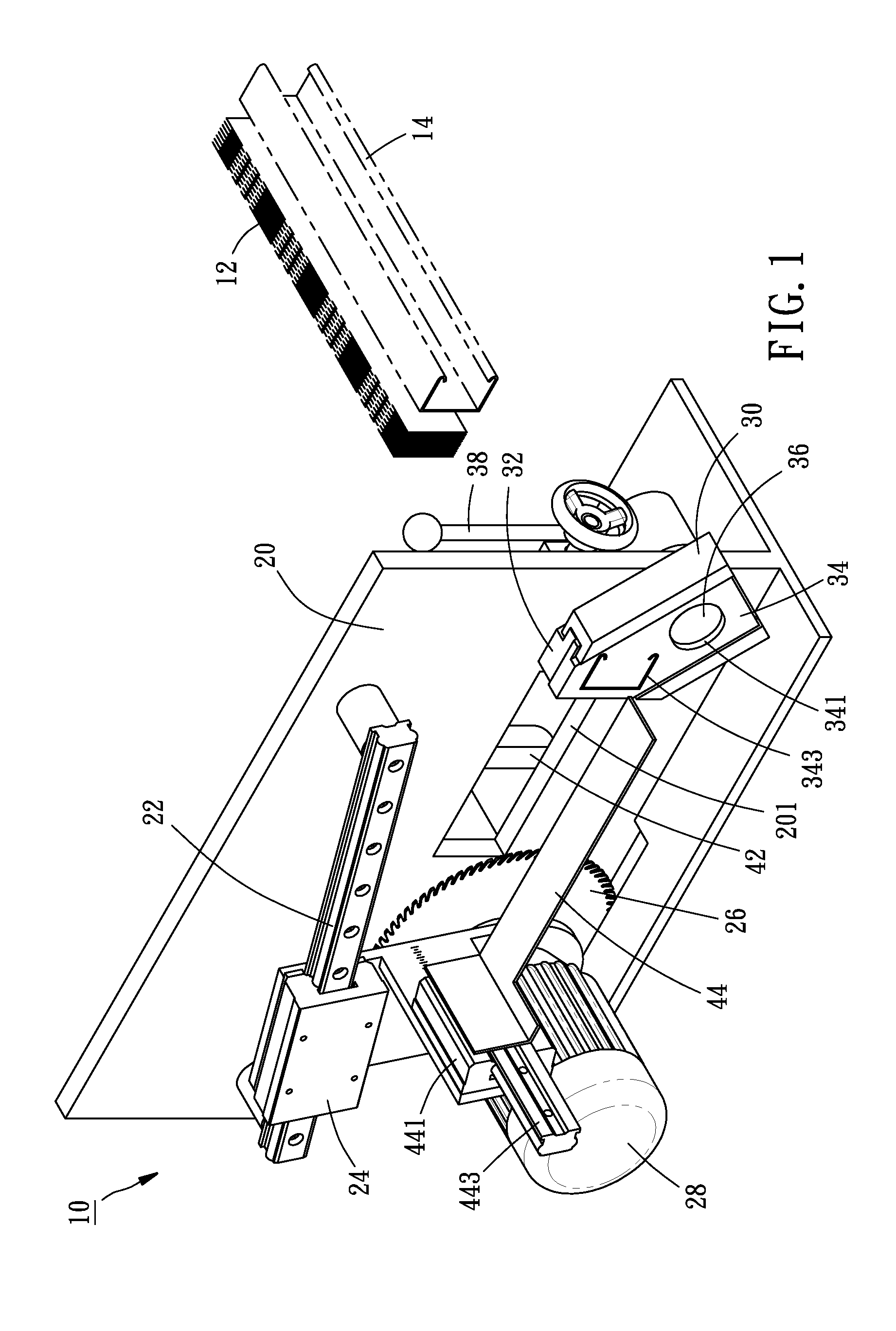
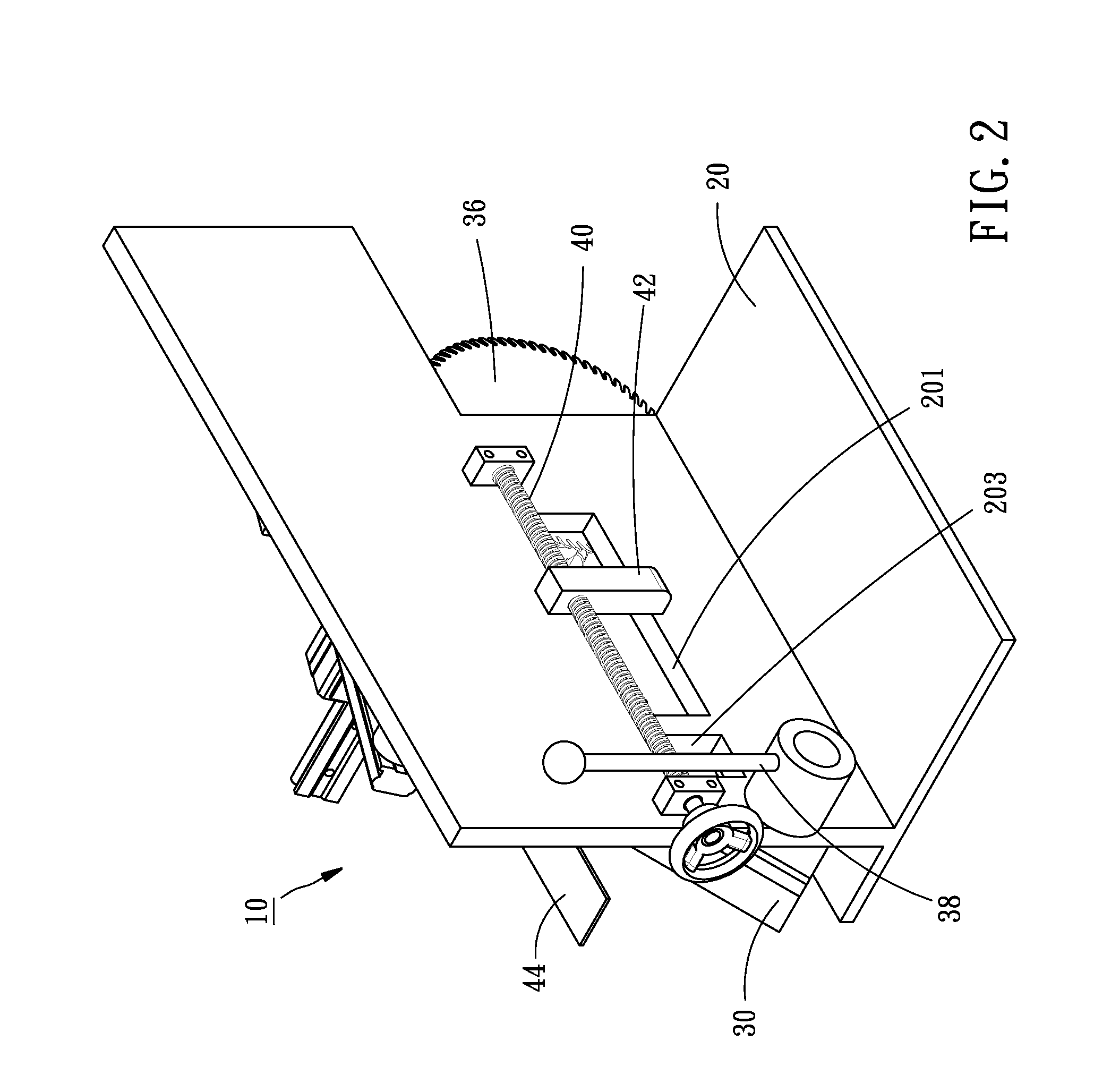
[0020]As shown in FIGS. 1 to 4, a blind cutter 10 for cutting slats 12 and a head rail 14 of a blind in accordance with a first preferred embodiment of the present invention comprises a base 20, a first rail 22, a slide block 24, a saw blade 26, a motor 28, a second rail 30, a fixed cutting blade 32, a movable cutting blade 34, a transmission rod 36, a handle 38, a screw 40, a clamp member 42, and a regulation plate 44.

[0021]The base 20 has a rectangular first through hole 201 for penetration of the slats 12, and a rectangular second through hole 203 for penetration of the head rail 14.

[0022]The first rail 22 is obliquely mounted to the front side of the base 20.

[0023]The slide block 24 is configured to the first rail 22 and slidable between a first position, as show in FIG. 5, and a second position, as shown in FIGS. 1 and 4. The first position is higher than the second position.

[0024]The saw blade 26 is rotatably connected with the slide block 24. When the slide block 24 is moved ...


PUM

PropertyMeasurementUnit
Gravityaaaaaaaaaa

Abstract

A blind cutter includes a base, a rail obliquely mounted to the base, a slide block slidably mounted to the rail and slidable between a first position and a second position that is lower than the first position, and a saw blade rotatably connected with the slide block. As a result, when a user pushes the slide block from the second position to the first position for cutting slats of a blind, the saw blade and the slide block can move back to the second position automatically because of gravity when the cutting action of the saw blade has been finished.

Description

BACKGROUND OF THE INVENTION[0001]1. Field of the Invention[0002]The present invention relates generally to a blind cutter for cutting a blind, and more specifically to a blind cutter that includes a saw blade capable of moving back to an initial position automatically when finishing the cutting action.[0003]2. Description of the Related Art[0004]U.S. Pat. No. 6,336,388 discloses a blind cut down machine, comprising a base, a rail mounted to the base, a block slidably mounted to the rail, a saw blade rotatably connected with the block and driven by an electric motor for cutting slats of a blind, a fixed plate fixed to the base, and a movable plate movably mounted to the base and carrying a cutting die for cutting a head rail of the blind. By means of the aforesaid design, a user can fasten the slats and the head rail of the blind to the base, and then move the saw blade and the movable plate to cut the slats and the head rail of the blind.[0005]However, when the cutting action of the...

Claims


Application Information

Patent Timeline
IPC IPC(8): B26D1/00B26D7/02
CPCB23D45/003B23D47/08B23D47/02B23D45/021Y10T83/408Y10T83/75
Inventor CHEN, CHIN-FU
Owner CHEN CHIN FU
Why Eureka
Try Eureka