
Screw head recess drive and corresponding driver tool and recess punch

a technology of driver tools and recesses, which is applied in the direction of screws, bolts, fastening means, etc., can solve the problems of insufficiently meeting the above listed functional requirements of conventional drive recesses and/or driver tools, low head height does not provide sufficient recess depth to transmit sufficient torque, etc., to achieve the effect of maximizing the breaking torqu

Inactive Publication Date: 2010-05-27
UNISTEEL TECH INT
View PDF22 Cites 34 Cited by
  • Summary
  • Abstract
  • Description
  • Claims
  • Application Information

AI Technical Summary

Benefits of technology

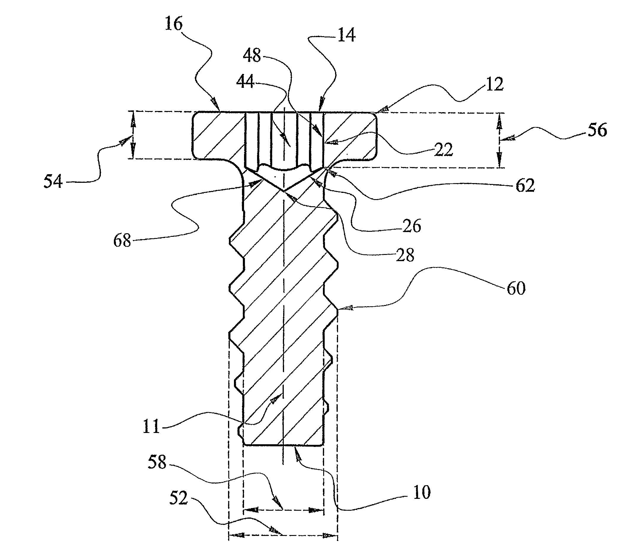
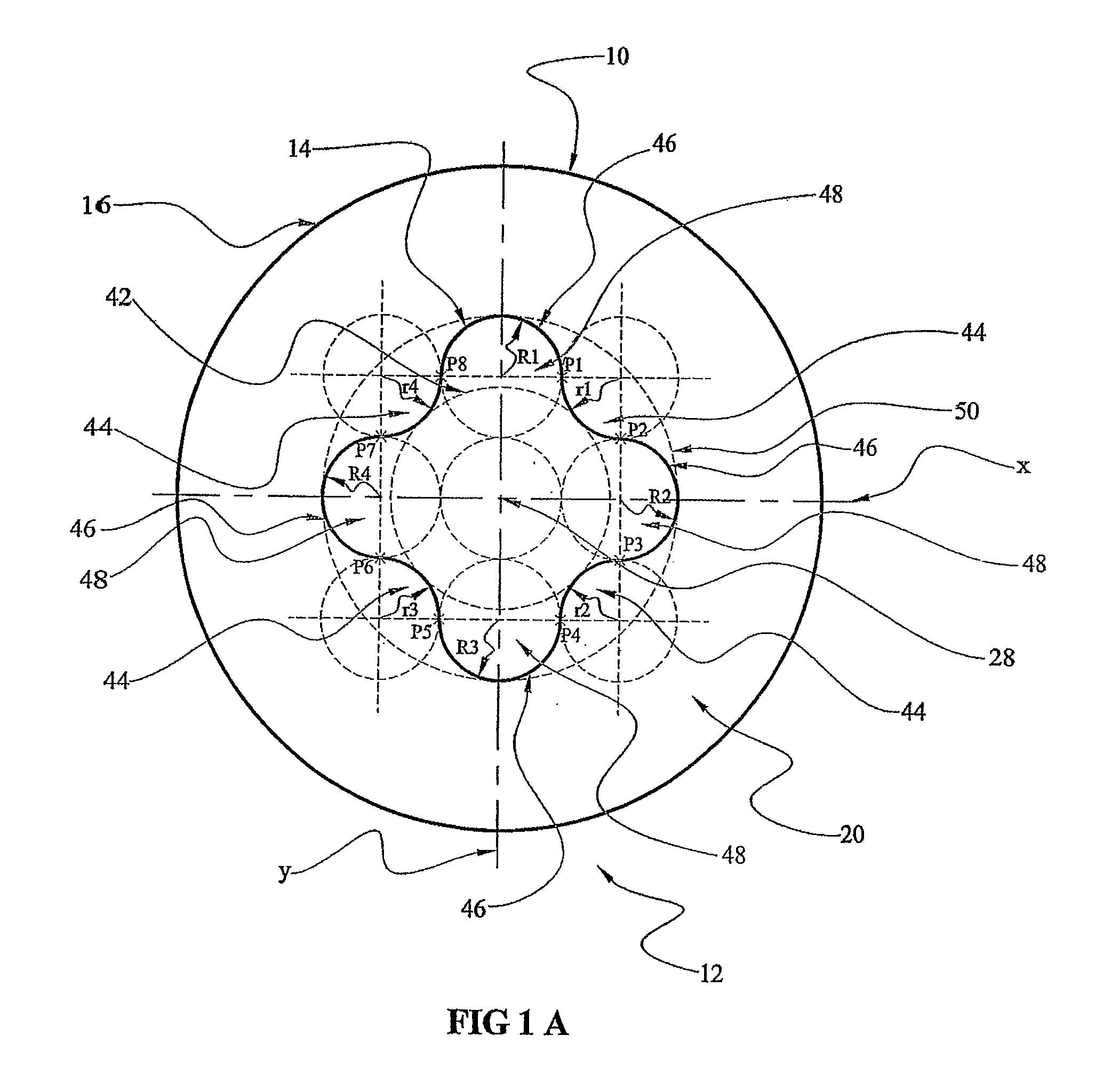
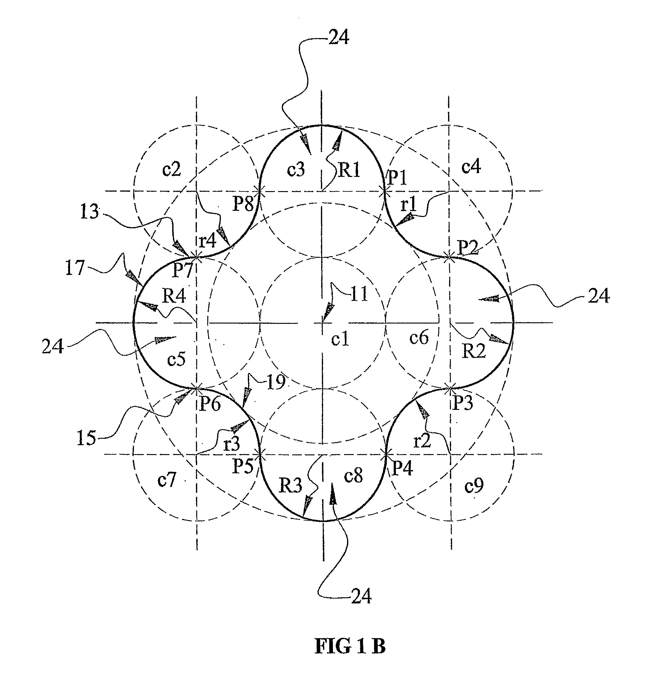
[0007]In an embodiment, the plurality of channels the first wall of each channel continuously and smoothly forms a wall with the second wall of an adjacent channel. A surface of recess side wall is substantially perpendicular with the top surface of the drive head. A surface of recess side wall may be tapered with the top surface of the drive head. In the fastener the head may be arranged in a substantially circular shape that defines a radius of the head. The top surface of the head may be substantially flat. The plurality of channel recesses may comprise four channel recesses. The fastener may further comprise a head to shank material ratio from the recess side wall to the side wall of the head of the fastener is arranged to maximize breaking torque. The head to shank material ratio may be at least 1:1. The recess has a recess depth and the fastener has a head height, wherein the head height is less than the recess depth. The head height may be in the range of 0.1 mm and of the recess depth. The head height may be in the range of 0.2 mm and the recess depth is 0.28 mm. The fastener may comprise a major diameter ranging from 0.4 mm to 2.0 mm, and a respective recess depth ranging from 0.28 mm to 0.80 mm. The first wall and second wall may be inner lobes and the recess side wall is an outer lobe. The radius of the first and second inner lobe walls may each equal with the radius of the recess side out lobe wall

Problems solved by technology

However, current conventional drive recesses and / or driver tools are unsuitable for situations where both quality and functional needs for installation are required and extra reliability and characteristic for miniature product and process applications.
However, as mentioned above, the conventional drive systems do not adequately meet all or some of the above listed of the functional requirements.
Although these previous screw head recess drives afford sure transmission of torque by virtue of their crossing recesses, and the driver bits fit in the recesses snugly and firmly, thereby improving operation efficiency in tightening or removing screws, there have arisen certain problems in particular relating to electrical device manufacturing where manufacturers are moving to miniaturization of their product, which directly has an impact on fasteners size to be designed with special quality, functional and reliability to meet the application needs which are higher than that of current industrial standards.
Such low head height does not provide sufficient recess depth to transmit sufficient torque in many applications.
Conventional screws in these applications have a functional limitation that is does not meet the functional requirements in the industry.

Method used


Image

  • Screw head recess drive and corresponding driver tool and recess punch
  • Screw head recess drive and corresponding driver tool and recess punch
  • Screw head recess drive and corresponding driver tool and recess punch

Examples


Embodiment Construction

[0024]Embodiments of a screw head recess in screw heads in accordance with the invention are disclosed. In addition, corresponding driver tools or bits to match the recesses are disclosed. The recesses in the screw heads are suited to transmit a high torque, compatible for automation assembly, and are high drive bit cycle and high failure torque tolerant. The recessed screw head and a corresponding driver bit, are described having different side wall configurations. One embodiment shown and described is a lobular recess drive embodiment having a straight wall configuration, as shown in FIG. 1-6. Another embodiment shown and described is a lobular recess drive embodiment having a tapered wall configuration, as shown in FIG. 7-12.

[0025]In the embodiments, the basic geometry and configuration of the top surface 16 are the same, as shown in FIG. 1A. However, the recess shapes in the embodiments are sculpted and adapted to transmit a high torque while also affording a larger cross sectio...


PUM

PropertyMeasurementUnit
recess depthaaaaaaaaaa
heightaaaaaaaaaa
diameteraaaaaaaaaa

Abstract

A fastener with a recess head wherein the drive head has four lobular recess channels. Each channel comprises a first wall, a second wall, a bottom surface and a recess sidewall. The first and second walls have portions opposing each other and a constant radius of curvature to form a continuously and smoothly forming wall of the channel. A torque producing driver tool is defined with cross sectional signature substantially complementary in size and shape of the recess of the drive head of the fastener for matable engagement. A recess punch for manufacturing the fastener is also defined and comprises a punch holder and a punch pin integral with the holder.

Description

FIELD OF THE INVENTION[0001]This invention relates to screw head recess drives and corresponding driver tool or bit capable of engaging with the screw head recess drive of a screw.BACKGROUND OF THE INVENTION[0002]Drive systems for all types of miniature screws typically for custom low profile head height product sizes range from about 0.4 mm through about 2.0 mm are conventionally used for special purpose applications. In such applications, threads and head height of the screw are custom designed to meet specific quality and functional requirements in joints. For example, when designs of screw head height are thinner than industrial standards, such as for example Japanese Camera Industrial Standard (JCIS), American National Standards Institute (ANSI), German Institute for Standardization (DIN) or International Organization for Standardization (ISO), deeper recess depth is required to achieve and transmit higher torque in joints. Another example is when assembling joints with thread ...

Claims


Application Information

Patent Timeline
Patent Type & Authority Applications(United States)
IPC IPC(8): F16B35/06B25B23/00B21J13/00
CPCB21K1/463B21K5/20F16B35/041F16B23/003B25B15/005F16B23/00B25B29/00B21H3/00B29B15/02
Inventor KARUPAYA, BALASINGAM
Owner UNISTEEL TECH INT
Learn More