Method and Apparatus for Distributing a Load About an Air Beam

Active Publication Date: 2010-06-10
DYNAMIC SHELTERS
View PDF24 Cites 4 Cited by
  • Summary
  • Abstract
  • Description
  • Claims
  • Application Information

AI Technical Summary

Benefits of technology

[0005]It is an object of the present invention to obviate or mitigate at least one disadvantage of previous methods and apparatus for distributing the attachment point loading for air beam structures.

Problems solved by technology

The pneumatic columns may be difficult to connect with other structural elements / attachments due to their relative weakness and susceptibility to puncture.
This can make them difficult to incorporate into structures and attachment to footings / anchors / guy wires, supports etc.

Method used


Image

  • Method and Apparatus for Distributing a Load About an Air Beam
  • Method and Apparatus for Distributing a Load About an Air Beam
  • Method and Apparatus for Distributing a Load About an Air Beam

Examples


Embodiment Construction

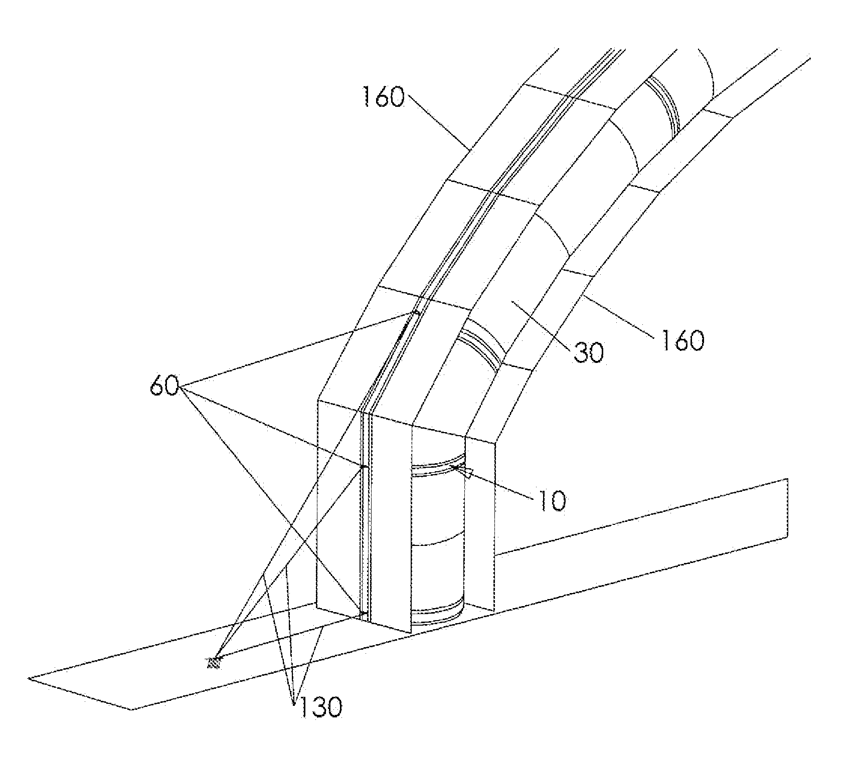
[0041]Generally, the present invention provides a method and system for providing an attachment connection for connecting with a pneumatic tubular columns (arches) such as air beams.

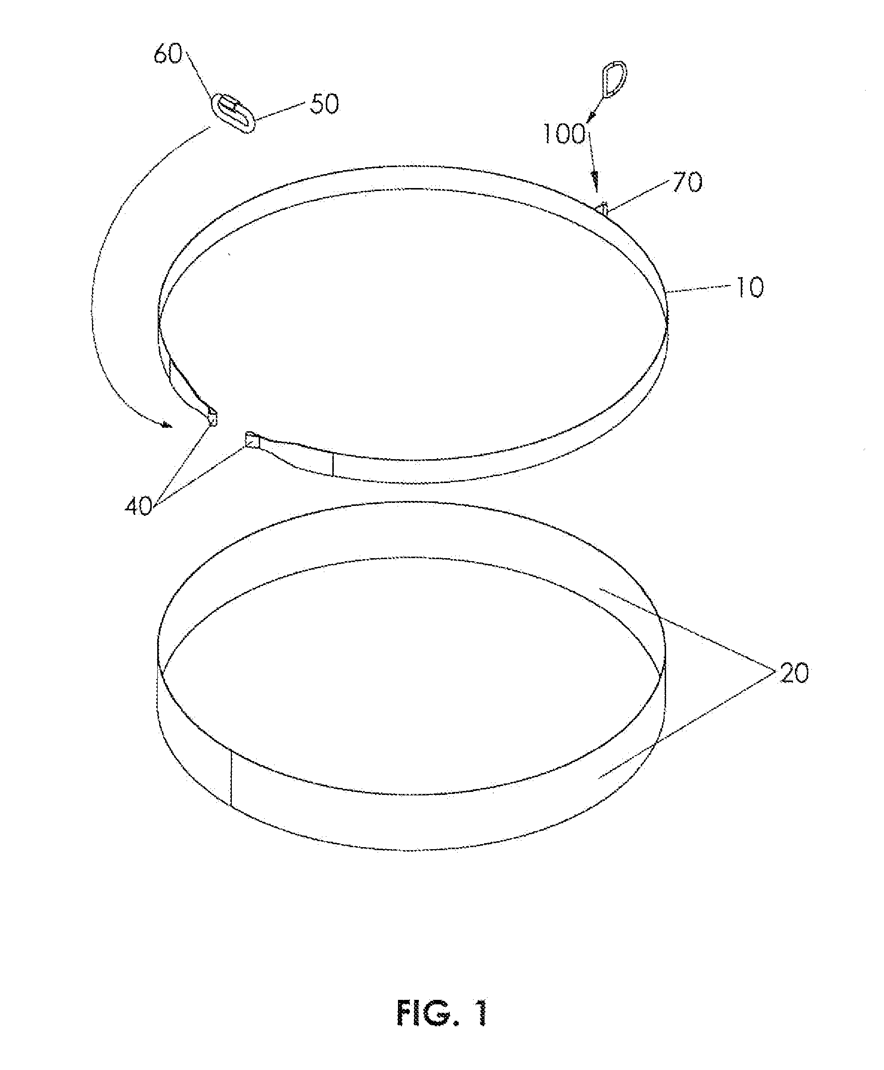
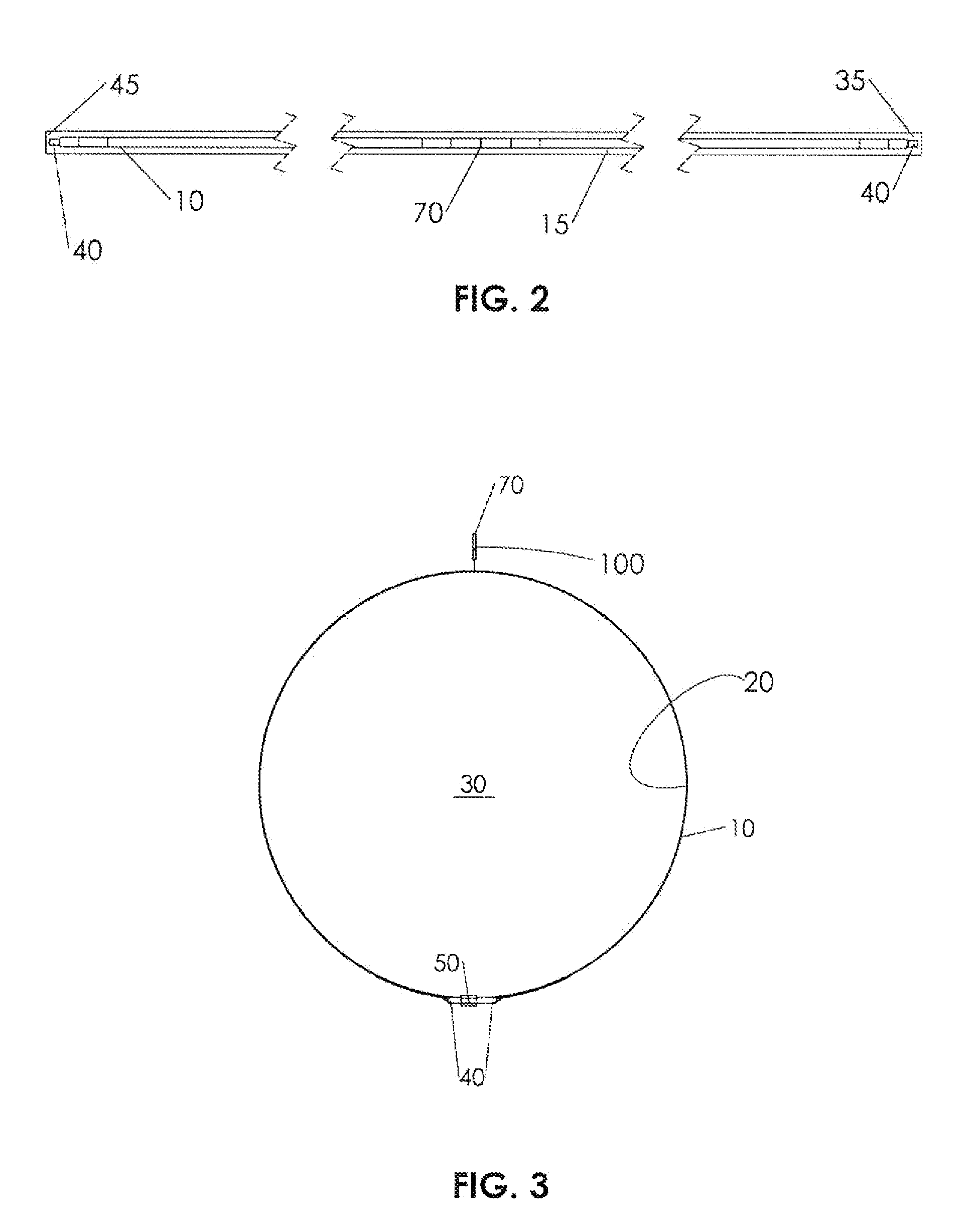
[0042]Referring to FIGS. 1-3, a hug strap 10 is attached to a hug strap pad 20. The hug strap pad 20 is then attached to an air beam 30 (FIG. 3). The hug strap pad 20 and hug strap 10 are connected by sewing, stitching, adhesive, or other means. This allows the hug strap 20 to be securely attached to the air beam 30 without risk to the pneumatic integrity of the air beam 30.

[0043]The connection between the hug strap 10 and the hug strap pad 20 may be intermittent or spot or may be substantially continuous along the perimeter (e.g. circumference for cylindrical tube shown). The hug strap pad 20 and the air beam 30 (FIG. 3) are connected by welding, bonding, adhesive, fusing, or other means. The connection between the hug strap pad 20 and the air beam 30 (FIG. 3) may be intermittent or spot or may be subst...


PUM


Abstract

An apparatus for connecting an attachment and an air beam comprising a hug strap attached to a hug strap pad, the hug strap adapted to connect with the attachment, and the hug strap pad adapted to attach to the air beam. A method of securing an attachment to an air beam comprising providing an air beam, attaching a hug strap to a hug strap pad, securing the hug strap pad (with the hug strap attached) to the air beam, and securing the attachment to the hug strap.

Description

CROSS REFERENCE TO RELATED APPLICATIONS[0001]This application claims the benefit of priority of U.S. Provisional Patent Application No. 61 / 094,727 filed Sep. 5, 2008, which is incorporated herein by reference in its entirety.FIELD OF THE INVENTION[0002]The present invention relates generally to static structures. More particularly, the present invention relates to air beam construction static structures.BACKGROUND OF THE INVENTION[0003]Inflatable structural members, commonly referred to as “air beams” may be assembled to form large inflatable shelters. The pneumatic columns may be difficult to connect with other structural elements / attachments due to their relative weakness and susceptibility to puncture. This can make them difficult to incorporate into structures and attachment to footings / anchors / guy wires, supports etc.[0004]It is, therefore, desirable to provide a method and apparatus for distributing the attachment point loading for air beam structures.SUMMARY OF THE INVENTION[...

Claims


Application Information

Patent Timeline
IPC IPC(8): E04C3/00E04H15/20F16B7/00
CPCE04C3/005Y10T403/19E04H2015/201E04C3/38
Inventor WARNER, HAROLDLUKASIEWICZ, STANISLAW A.
Owner DYNAMIC SHELTERS
Why Eureka
Try Eureka